23
5.6 Alarm/Event Setpoints
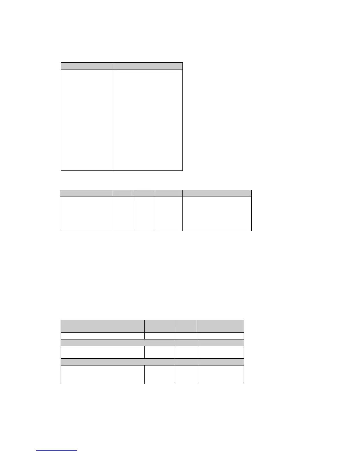
Table 5-11 Setpoint Setup Locations
Setpoint number Setup indexes (hex)
Setpoint #1 8200h-8205h
Setpoint #2 8206h-820Bh
Setpoint #3 820Ch-8211h
Setpoint #4 8212h-8217h
Setpoint #5 8218h-821Dh
Setpoint #6 821Eh-8223h
Setpoint #7 8224h-8229h
Setpoint #8 822Ah-822Fh
Setpoint #9 8230h-8235h
Setpoint #10 8236h-820Bh
Setpoint #11 823Ch-8241h
Setpoint #12 8242h-8247h
Setpoint #13 8248h-824Dh
Setpoint #14 824Eh-8253h
Setpoint #15 8254h-8259h
Setpoint #16 825Ah-825Fh
Table 5-12 Setpoint Setup Registers
Parameter Offset Length Direction Range
Trigger ID +0 4 R/W see Table 5-13
Action +1 4 R/W see Table 5-14
Operate delay +2 4 R/W
0-9999 (×0.1 sec)
Release delay +3 4 R/W
0-9999 (×0.1 sec)
Operate limit +4 8 R/W see Table 5-13
Release limit +5 8 R/W see Table 5-13
1.
The setpoint is disabled when its trigger parameter is set to NONE. To disable the setpoint, write zero
into this register.
2. When writing the setpoint registers (except the event when the setpoint is to be disabled), it is
recommended to write all the setpoint registers using a single request, or to disable the setpoint before
writing into separate registers. Each written value is checked for compatibility with the other setpoint
parameters; if the new value does not conform to these, the request will be rejected.
3. Operate and release limits for the trigger parameters and their ranges are indicated in Table 5-13.
Limits indicated as N/A are read as zeros. When writing, they can be omitted or should be written as
zeros.
4. When a setpoint action is directed to a relay allocated to output energy pulses, an attempt to re-allocate
it for a setpoint will result in a negative response.
Table 5-13 Setpoint Triggers
Trigger parameter Trigger
index (hex)
Unit Range
c
None
0000h N/A
Phase reversal
Positive phase rotation reversal
d
8901h N/A
Negative phase rotation reversal
d
8902h N/A
High/low real-time values on any phase
High voltage
f
0E00h V 0 to Vmax
Low voltage
f
8D00h V 0 to Vmax
High current 0E01h A 0 to Imax

 Loading...


