26
10-15 Reserved
Options 2 0-2 Number of relays - 1
3-15 Reserved
5.9 Extended Status Registers
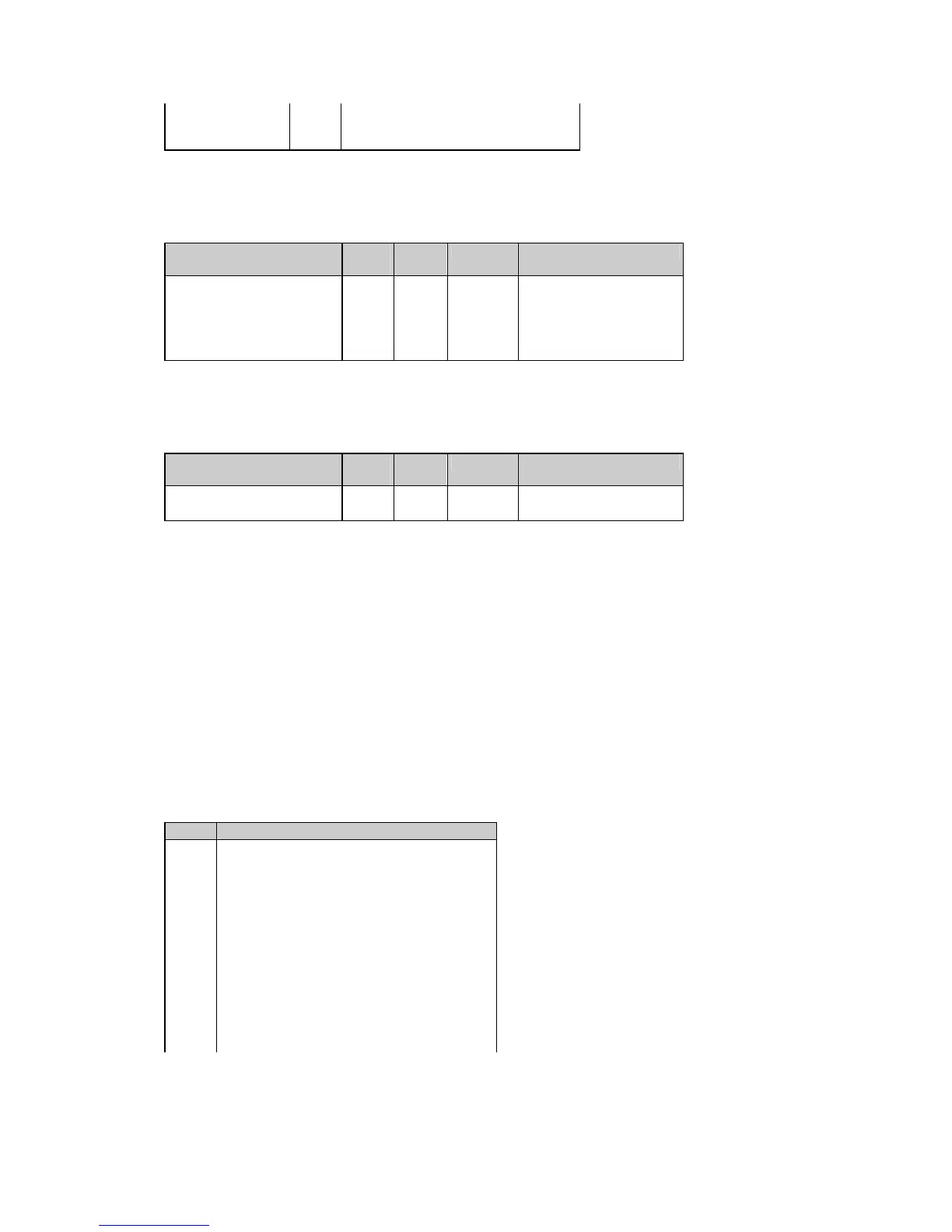
Table 5-19 Extended Status Registers
Parameter Data
index
Length Direction Range
Relay status 7D00h 4 R see Table 4-12
Reserved 7D01h 4 R read as 0000
Reserved 7D02h 4 R read as 0000
Setpoint status 7D03h 4 R see Table 4-13
Log status 7D04h 4 R see Table 4-14
5.10 Alarm Status Registers
Table 5-20 Alarm Status Registers
Parameter Data
index
Length Direction Range
Setpoint alarm status 7E00h 4 R/W see Table 5-21
Self-check alarm status 7E01h 4 R/W see Table 5-22
The setpoint alarm register stores the status of the operated setpoints by setting the appropriate bits to 1.
The alarm status bits can be reset all together by writing zero to the setpoint alarm register. It is possible to
reset each alarm status bit separately by writing back the contents of the alarm register with a
corresponding alarm bit set to 0.
The self-check alarm register indicates possible problems with the instrument hardware or setup
configuration. The hardware problems are indicated by the appropriate bits which are set whenever the
instrument fails self-test diagnostics or in the event of loss of power. The setup configuration problems are
indicated by the dedicated bit which is set when either configuration register is corrupted. In this event, the
instrument will use the default configuration. The configuration corrupt bit may also be set as a result of the
legal changes in the setup configuration since the instrument might implicitly change or clear other setups if
they are affected by the changes made.
Hardware fault bits can be reset by writing zero to the self-check alarm register. The configuration corrupt
status bit is also reset automatically when you change setup either via the front panel or through
communications.
Table 5-21 Setpoint Alarm Status
Bit Description
0 Alarm #1
1 Alarm #2
2 Alarm #3
3 Alarm #4
4 Alarm #5
5 Alarm #6
6 Alarm #7
7 Alarm #8
8 Alarm #9
9 Alarm #10
10 Alarm #11
11 Alarm #12
12 Alarm #13
13 Alarm #14

 Loading...


