17
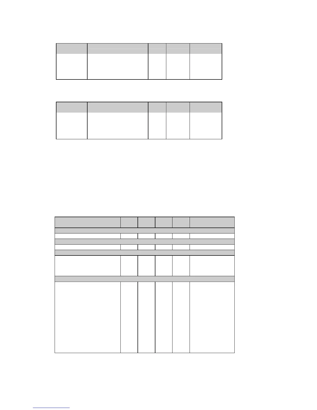
Table 5-5 User Assignable Registers
Data index
(hex)
Register contents Length Direction Range
8000h User definable data 0
c
c
c
8001h User definable data 1
c
c
c
8002h
...
User definable data 2
...
c
...
c
c
8077h User definable data 119
c
c
c
c
- depends on the mapped register
Table 5-6 User Assignable Register Map
Data index
(hex)
Register contents Length Direction Range
8100h Data index for user data 0 4 R/W 0000h-FFFFh
8101h Data index for user data 1 4 R/W 0000h-FFFFh
8102h
...
Data index for user data 2
...
4
...
R/W 0000h-FFFFh
8177h Data index for user data 119 4 R/W 0000h-FFFFh
To build your own register map, write to map registers (8100h to 8177h) the actual addresses you want to
read from or write to via the assignable area (8000h to 8077h). For example, if you want to read registers
0C00h (real-time voltage of phase A) and 1700h (kWh import) via indexes 8000h-8001h, do the following:
- write 0C00h to register 8100h
- write 1700h to register 8101h
Reading from registers 8000h-8001h will return the voltage reading in register 8000h, and the kWh reading
in register 8001h.
5.2 Extended Data Registers
Table 5-7 Extended Data Table
Parameter Data
index
Length Direc-
tion
Unit Range c
None
None 0000h 4 R 0
Relays
Relay status
0800h 4 R see Table 4-12
Event/time counters
Counter #1 0A00h 8 R/W 0 to 99999
Counter #2 0A01h 8 R/W 0 to 99999
Counter #3 0A02h 8 R/W 0 to 99999
Counter #4 0A03h 8 R/W 0 to 99999
Real-time values per phase (power values - P)
Voltage L1/L12
f
0C00h 8 R V 0 to Vmax
Voltage L2/L23
f
0C01h 8 R V 0 to Vmax
Voltage L3/L31 f 0C02h 8 R V 0 to Vmax
Current L1 0C03h 8 R A 0 to Imax
Current L2 0C04h 8 R A 0 to Imax
Current L3 0C05h 8 R A 0 to Imax
kW L1 0C06h 8 R kW -Pmax to Pmax
kW L2 0C07h 8 R kW -Pmax to Pmax
kW L3 0C08h 8 R kW -Pmax to Pmax
kvar L1 0C09h 8 R kvar -Pmax to Pmax
kvar L2 0C0Ah 8 R kvar -Pmax to Pmax
kvar L3 0C0Bh 8 R kvar -Pmax to Pmax
kVA L1 0C0Ch 8 R kVA 0 to Pmax
kVA L2 0C0Dh 8 R kVA 0 to Pmax

 Loading...


