16
5.1.2 Variable-Size Direct Read/Write
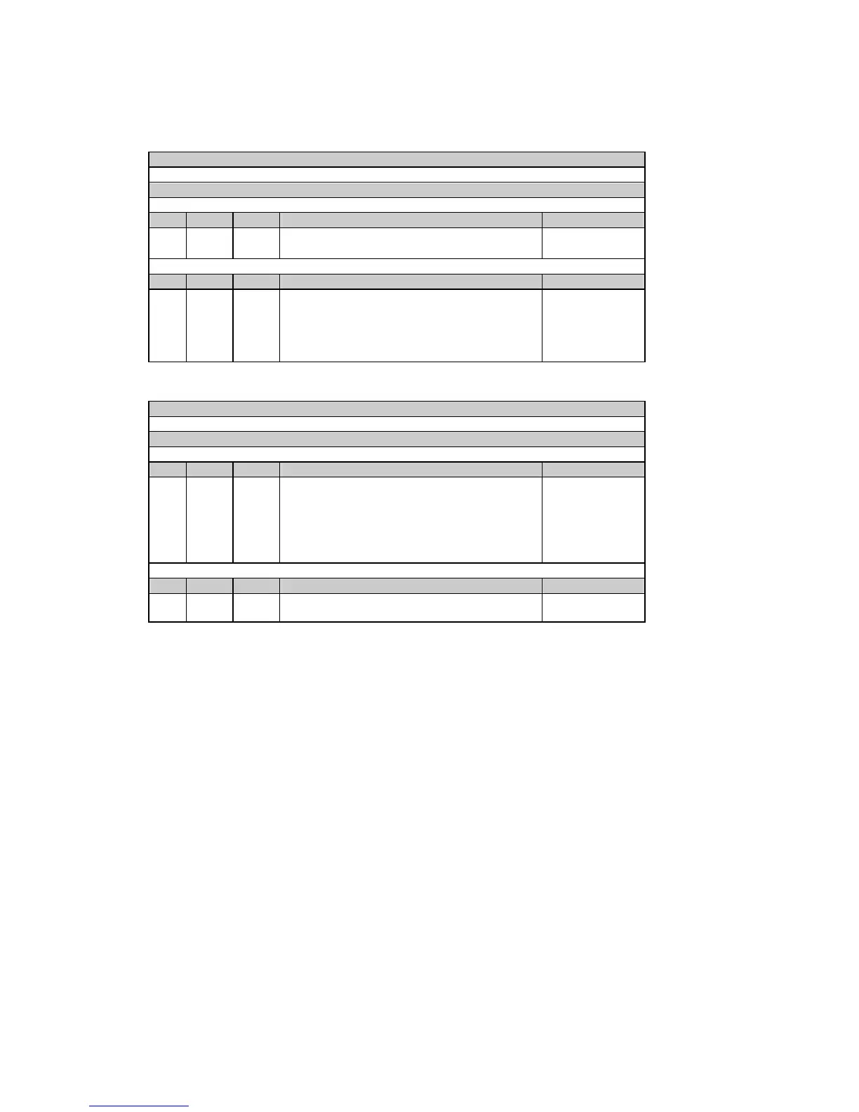
Table 5-3 Read Request
Message type (ASCII)
X
Message body (hexadecimal)
Request
Field Offset Length Parameter Range
1 0 4 Start data index to read 0000h - FFFFh
2 4 2 The number of contiguous data items to read 1-61 (01h - 3Dh)
Response
Field Offset Length Parameter Range
1 0 2 Number of data items in the message 1-61 (01h - 3Dh)
2 2 2/4/8 Data #1 value
3 2/4/8 Data #2 value
... ... ... ...
60 2/4/8 Data #60 value
Table 5-4 Write Request
Message type (ASCII)
x
Message body (hexadecimal)
Request
Field Offset Length Parameter Range
1 0 4 Start data index to write 0000h - FFFFh
2 4 2 The number of contiguous data items to write 1-61 (01h - 3Dh)
2 2 2/4/8 Data #1 value
3 2/4/8 Data #2 value
... ... ... ...
60 2/4/8 Data #60 value
Request
Field Offset Length Parameter Range
1 0 4 Start data index written 0000h - FFFFh
2 4 2 The number of data items written 1-61 (01h - 3Dh)
With variable-size direct read/write messages, data items are read and written as 2, 4 or 8-character
hexadecimal numbers. The actual data size is indicated for each data location. When written, the data
format should be exactly the same as indicated.
The number of parameters that can be read or written by a single read/write request depends on the size
of each data item. The total length of all parameters should not exceed 240 characters.
5.1.3 User Assignable Registers
The instrument contains 120 user assignable registers in the range of indexes 8000h to 8077h (see Table
5-5). You can map any of these registers to either register index, accessible in the instrument through
direct read/write requests. Registers that reside in different locations may be accessed by a single request
by re-mapping them to adjacent addresses in the user assignable registers area.
The actual indexes of the user assignable registers which are accessed via indexes 8000h to 8077h are
specified in the user assignable register map. It occupies indexes 8100h to 8177h (see Table 5-6), where
the map register 8100h should contain the actual index of the register accessed via assignable register
8000h, register 8101h should contain the actual index of the register accessed via assignable register
8001h, and so on. Note that the user assignable register indexes and the user register map indexes may
not be re-mapped.

 Loading...


