Chapter 4 Setup Menus 27
the entire range for power factor from -0 to +0, the scales would be specified as -
0.000/0.000.
3. For bi-directional analog output (±1 mA), the zero scale corresponds to the
center of the scale range (0 mA) and the direction of current matches the sign of
the output parameter. For signed (bi-directional) values, such as powers and
signed power factor, the scale is always symmetrical with regard to 0 mA, and the
full scale corresponds to +1 mA output for positive readings and to -1 mA output for
negative readings. For these, the zero scale (0 mA output) is permanently set in
the instrument to zero for all parameters except the signed power factor for which it
is set to 1.000, and may not change. Unsigned parameters are output within the
current range 0 to +1 mA and can be scaled using both zero and full scales as in
the case of single-ended analog output.
4. When the analog scale value exceeds the number of places in the window, it is
converted to higher units (for instance, kW to MW) and a decimal point is placed in
the window to indicate the new measurement range.
5. Each time you select the output parameter for the analog channel, its zero and
full scales are set by default to the lower and upper parameter limits, respectively.
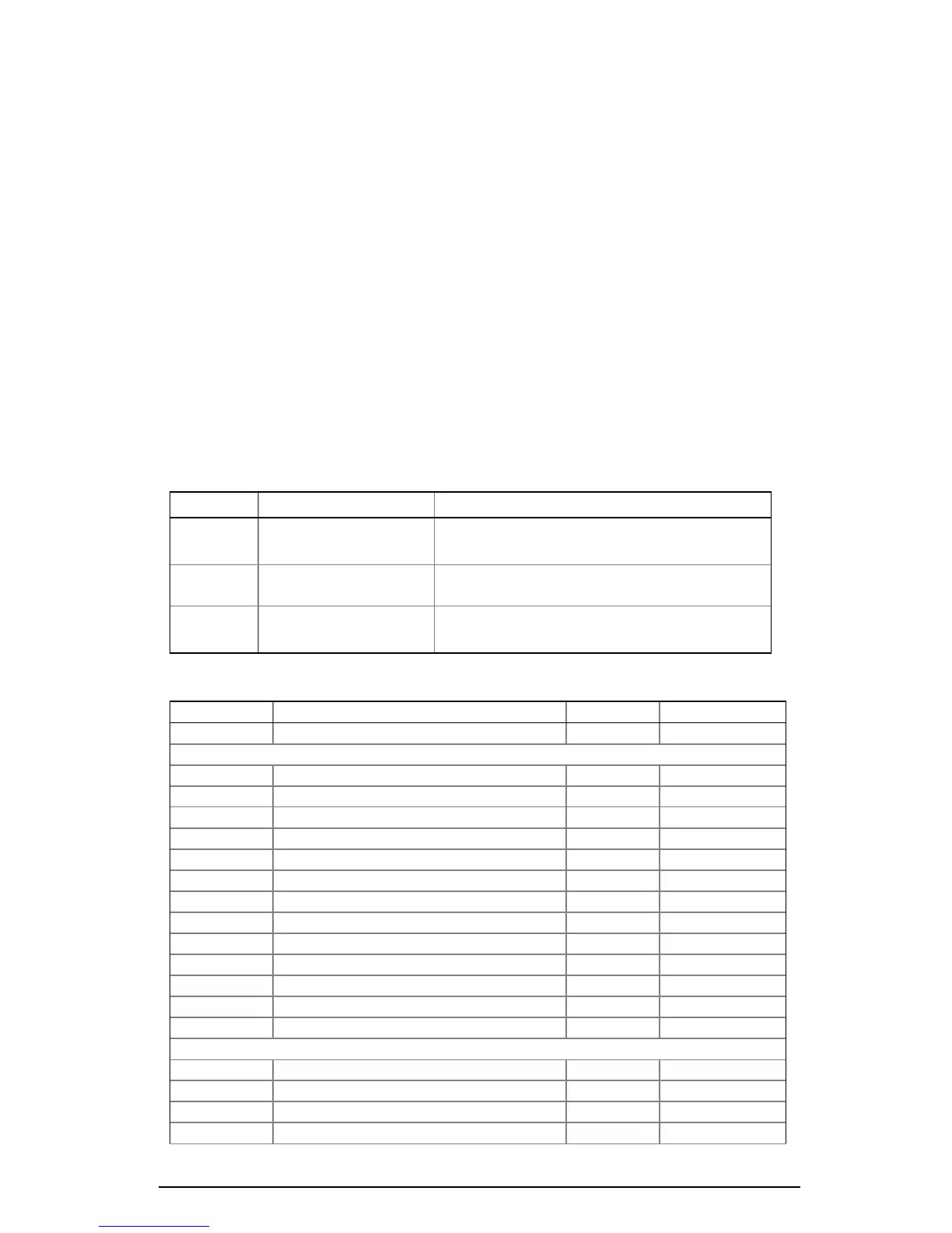
Table 4-3 Analog Output Setup Options
Code Option Description
OutP Output parameter The output parameter for the analog output
channel
Lo Zero scale (0/4 mA) The reading of the parameter corresponding
to a zero-scale current output
Hi Full scale (1/20 mA) The reading of the parameter corresponding
to a full-scale current output
Table 4-4 Analog Output Parameters
Code Parameter Unit Scale
1
nonE Output disabled 0
Real-time Measurements
rt U 1 Voltage L1/L12
3
V/kV 0 to Vmax
rt U 2 Voltage L2/L23
3
V/kV 0 to Vmax
rt U 3 Voltage L3/L31
3
V/kV 0 to Vmax
rt C1 Current L1 A 0 to Imax
rt C2 Current L2 A 0 to Imax
rt C3 Current L3 A 0 to Imax
rt P Total kW kW/MW -Pmax to Pmax
rt q Total kvar kvar/Mvar -Pmax to Pmax
rt S Total kVA kVA/MVA 0 to Pmax
rt PF Total PF -0.000 to 0.000
rt PF.LG Total PF lag 0 to 1.000
rt PF.Ld Total PF lead 0 to 1.000
rt Fr Frequency Hz 0 to 100.00
2
Average Measurements
Ar U 1 Voltage L1/L12
3
V/kV 0 to Vmax
Ar U 2 Voltage L2/L23
3
V/kV 0 to Vmax
Ar U 3 Voltage L3/L31
3
V/kV 0 to Vmax
Ar C1 Current L1 A 0 to Imax

 Loading...


