Chapter 2 Installation 11
2.2 Electrical Installation
) Before installation ensure that all incoming power
sources are shut OFF. Failure to observe this practice
can result in serious or even fatal injury and damage to
equipment.
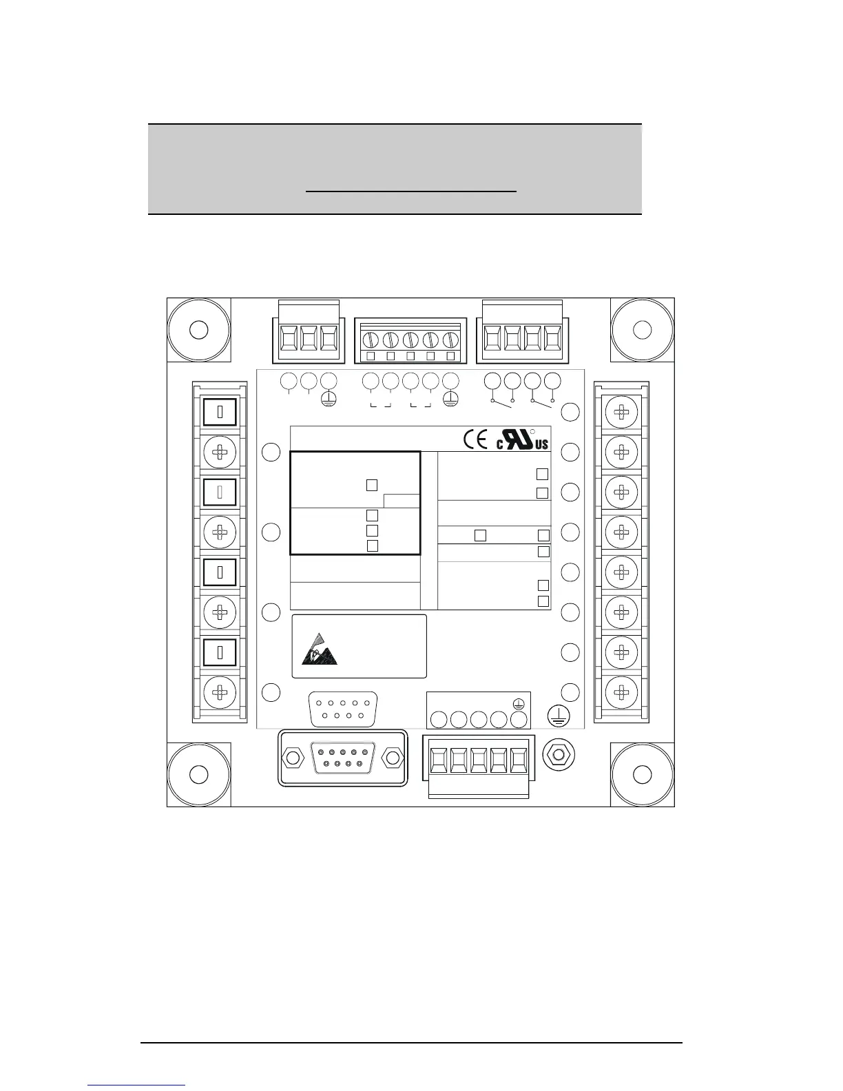
Connections to the PM172EH are made via terminals located on the rear
panel of the instrument as shown in Figure 2-6.
2
RELAYS
NOM. VOLT. MEASUREMENT
N/-
L/+
POWER SUPPLY
COMM. PROTOCOL
Devices
RS-422/485
Static-Safe
Workstations
Handle Only at
11
V
9
N
5
RS-232
COM.1
13 161514 17
-RX
RS-422/RS-485
-TX
6
13
1
+TX +RX
16 171514
COM.2
STATUS INPUT
ANALOG OUTPUT
POWER SUPPLY
10-16VDC
18-36VDC
36-72VDC
ATTENTION
SW. VER
S/N
Static-Sensitive
(24)
5
V
V
8
3
(48)
2
V
2
1
50/60Hz
85-290VDC
(12)
90-264VAC
CT.
5A
I
1A
CT.
ASCII & DNP3.0
ANALOG OUTPUT
ASCII & MODBUS
S
INPUT
N
O
120V (OPT. U)
690V
STANDARD
10W
LOW DC
P
T
O
R
12
18 19
20
18 19 20
2523
1
+
-
2221
-
2
+
24 26
1
27 28
26
27 28
10
00-06007
12
6
I
-
9
3
+
7
-
2
I
+
4
-
3
1
I
+
1
29
29
Figure 2-6 Terminals - Rear View
2.2.1 Power Source Connection
The power source can be dedicated-fused, or from a monitored voltage if
it is within the instrument’s power supply range.
AC power supply: line to terminal 12; neutral to terminal 10.
DC power supply: positive to terminal 12; negative to terminal 10.

 Loading...


