Appendix B Using Setpoints
71
Appendix B Using Setpoints
9. Appendix B Using Setpoints
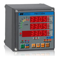
The PM172EH has an embedded logical controller that can run different
actions in response to user-defined internal and external events. Unlike a
PLC, the PM172EH uses a simplified setpoint programming technique
that allows the user to define a logical expression based on measured
analog and digital values that will produce a required action.
The PM172EH provides 16 setpoints with programmable operate and
release delays. Each setpoint can evaluate a logical expression with up to
four arguments using OR/AND logic. Whenever an expression is
evaluated as “true”, the setpoint performs up to four consequent actions
that can send a command to the output relays, increment or decrement a
counter, or trigger a recorder.
The scan time for all setpoints is 50 ms.
Using Logical Expressions
Logical operators OR/AND are treated in a simplified manner. They have
no specific priority or precedence rules.
Any trigger condition bound to the logical expression by the OR operator
and evaluated as “true” will override any preceding condition evaluated as
“false”. Similarly, any trigger condition evaluated as “false” and bound by
the AND operator will override any condition evaluated before it as “true”.
To avoid confusion, it is recommended not to alternate different logical
operators in one expression. Instead, bring all conditions that use the
same logical operator together to one side of the expression, and the
others - to the opposite side.
To explicitly override all other conditions with the critical trigger, put it at
the end of the expression using the OR operator if you want the setpoint
to be operated anyway when the trigger condition is asserted, and with
the AND operator, if the setpoint should not be operated while the critical
trigger is not asserted.
Using Numeric Triggers
For numeric (analog) triggers, a setpoint allows you to specify two
thresholds for each trigger to provide hysteresis (dead band) for setpoint
operations. The operate limit defines the operating threshold, and the
second release limit defines the release threshold for the trigger. The
trigger thresholds are specified in primary units.
If you do not want to use hysteresis for the trigger, set the release limit to
the same as the operate limit.

 Loading...