SATEL VERSA 9
5.4.1 Description of the mainboards
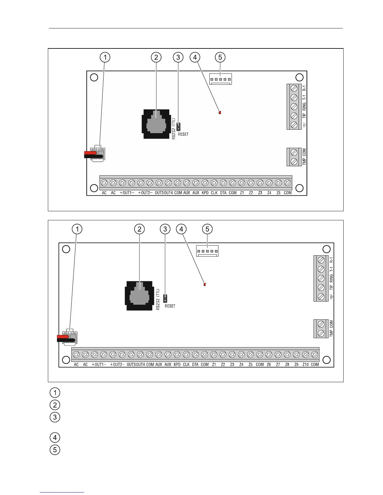
Fig. 2. Mainboard of VERSA 5 control panel.
Fig. 3. Mainboard of VERSA 10 control panel.
battery connection cables (red +, black -).
RS-232 (TTL) port.
RESET pins for emergency starting the control panel (see: “Emergency procedure of the
control panel start-up” p. 23).
DIALER LED. Indicates the status of control panel telephone communicator.
socket for connecting the INT-VG voice module, CA-64 SM voice synthesizer expander
or SM-2 synthesizer.