18 VERSA SATEL
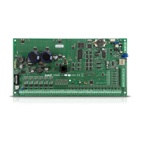
Fig. 20. Setting the address, as in the case of the INT-IT / INT-IT-2 module.
5.5.9 Connecting voice module / voice synthesizer expander
One INT-VG module / CA-64 SM expander can be connected to the control panel. It allows
recording of voice messages that will be used for telephone notification of events. In addition,
the INT-VG module offers the ability to operate the control panel from the telephone keypad
(interactive voice menu).
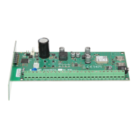
Address 23 (17h) must be set in the module / expander. The switch 7 in INT-VG module is
used to define how the device is to be identified by the control panel (OFF – INT-VG; ON –
CA-64 SM). The switch 8 disables / enables the recording of messages by means of built-in
microphone in both devices.
Fig. 21. Setting address in the INT-VG module / CA-64 SM expander. Recording of voice
messages is disabled (switch 8 in OFF position).
Connect the CLK and DTA terminals (INT-VG) / wires (CA-64 SM) to the communication bus
of the alarm control panel, and the plug to the dedicated socket.
5.6 Connecting the detectors
How the detector is connected to the zone must be suitable for the configuration chosen for
that zone. The zones on the control panel mainboard support the following configurations:
NC – the wiring type dedicated to connecting devices with the NC (normally closed) alarm
output. Opening the circuit will trigger an alarm.
NO – the wiring type dedicated to connecting devices with the NO (normally open) alarm
output. Closing the circuit will trigger an alarm.
EOL – this wiring type may be used to connect devices having the NC or NO alarm output.
Closing or opening the circuit will trigger an alarm.