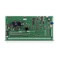
SATEL VERSA 21
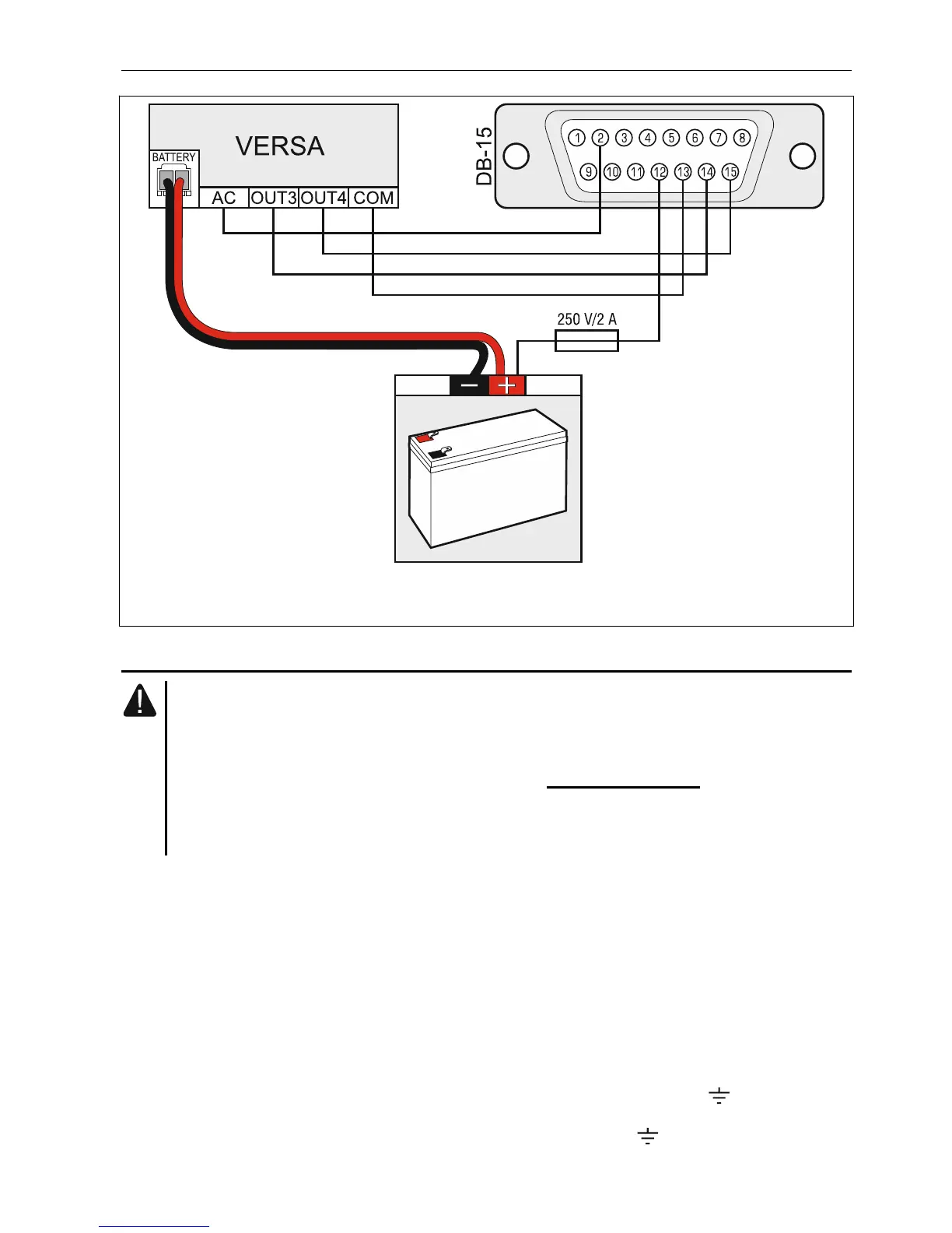
Fig. 24. Connecting the NOKTON NR2-DSC transmitter to the control panel. The DB-15
female connector is shown from the solder side.
5.9 Connecting the analog telephone line
Do not send telephone signals and alarm system signals by one multicore cable.
This may cause damage to the system in case of a high-voltage punch-through
coming from the telephone.
The control panel may only be connected to analog PSTN lines.
The system installer should inform the user about the way of connecting the
control panel to the telephone network.
The control panel must be connected directly to the telephone line (terminals marked TIP,
RING). Other devices using the telephone line (e.g. telephone, fax) should be connected
after the control panel (terminals marked T-1, R-1). Hence the telephone line should be
connected to the control panel using a four-wire cable. When connected in this manner, the
control panel will be able to completely capture the line for the time of making a call. This will
prevent the control panel telephone dialer from being blocked, e.g. by lifting the telephone
receiver (such a situation would take place, if the control panel was connected to the
telephone line after the telephone set).
If the ADSL service is used on the premises where the control panel is installed, the control
panel should be connected after the ADSL filter, and the other devices using the analog
telephone line should be connected to the control panel.
To protect the telephone communicator against over-voltage, connect the terminal to the
protective earth conductor (PE) of the 230 V AC mains. To make the connection, use
a conductor with ≥0,75 mm
2
cross-section. Never connect the terminal to the neutral
conductor (N).