SATEL VERSA 15
Depending on the controller, set the DIP-switches as required:
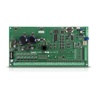
ACU-120 / ACU-270: switch 8 to ON position, the status of the other switches being
irrelevant,
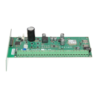
ACU-100: switches 4, 7 and 8 to ON position, and the other ones to OFF position (address 8
(08h) and the VERSA control panel compatibility mode enabled),
ACU-250: switch 4 to ON position, and the other ones to OFF position (address 8 (08h)).
All controllers of the ABAX wireless system are identified by the control panel as the
ACU-100 controller.
If the ACU-120 / ACU-270 / ACU-100 / ACU-250 controller is connected to the control
panel, installation of the VERSA-MCU controller in the system is impossible.
Fig. 13. Setting the DIP-switches in the ACU-120 / ACU-270 controller.
Fig. 14. Setting the DIP-switches in the ACU-100 controller.
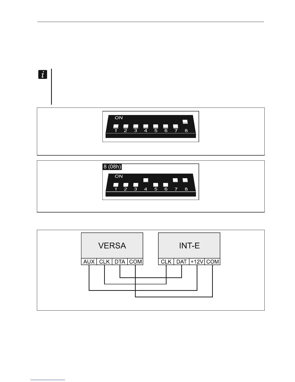
5.5.6 Connecting the hardwired zone expanders
Fig. 15. Connecting the INT-E expander to the control panel.
Up to three INT-E / CA-64 E / CA-64 EPS expanders can be connected to the control panel.
This enables expansion of the system by adding up to 24 programmable wired zones. Using
the expander DIP-switches:
set an address within the range from 12 (0Ch) to 14 (0Eh) – switches 1-5,
define how the expander is to be identified – switch 10 (INT-E) or 8 (CA-64 E /
CA-64 EPS).