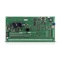
SATEL VERSA 23
5.10.3 Control panel power-up / start-up procedure
1. De-energize the 230 V AC circuit to which the transformer is to be connected.
2. Connect the 230 V AC wires to the terminals of transformer primary winding.
3. Connect the terminals of transformer secondary winding to the control panel AC
terminals. To make the connection, use flexible conductors with a cross-section of 0.5 –
0.75 mm
2
, or rigid conductors with a cross-section of 1 – 2.5 mm
2
.
4. Connect the battery to the dedicated leads (positive terminal to RED lead, negative
terminal to BLACK lead). If the battery has screw-type cable lugs, use adapters delivered
with the control panel (do not cut off the battery cable lugs). The control panel will not
start after connecting the battery alone.
5. Turn on 230 V AC power supply in the circuit to which the transformer is connected.
The control panel will start operating.
The above mentioned power-up sequence (first the battery, then the 230 V AC mains)
will ensure proper operation of the power supply unit and the electronic protection
circuits, thus preventing damage to the alarm system components caused by
installation mistakes, if any.
If it is necessary to de-energize the control panel, turn off the main power supply (AC)
first, and the backup power supply (battery) afterwards. Observe the above described
procedure when reconnecting the power supply.
5.10.4 Emergency procedure of the control panel start-up
If the control panel fails to start properly, keypads are not supported, codes are not accepted
by the control panel etc., despite all connections having been made correctly, follow the steps
below:
1. Turn off the control panel power supply (first disconnect the AC power, and then the
battery).
2. Put a jumper on the RESET pins.
3. Turn on the control panel power supply (first connect the battery and then the AC power).
4. Wait a few seconds and remove the jumper from the RESET pins. The control panel will
enter the service mode. The service mode menu will be displayed on the keypad with the
lowest address (in the case of a wireless keypad, the menu will be displayed on pressing
any key).
If the S
ERVICE MODE FROM RESET PINS option is disabled in the control panel then,
depending on the type of keypad in which the lowest address is set:
LCD: the , and (of the second partition) LEDs will be lit, and the
message “Restore factory settings ? 1=Yes” will come up on the display,
LED: the and (of the second partition) LEDs will be lit and the
LED will
be blinking rapidly.
Pressing the key will reset the control panel to its factory settings, but will enable
entering the service mode.
5.10.5 First steps after starting-up the control panel
Having started the control panel with factory defaults:
1. Set individual, correct addresses in the keypads.
2. Run the identification function for devices connected to the communication bus of the
control panel.