16 VERSA SATEL
For detailed information on how the expander will be identified and what are the functional
differences resulting from the identification, please refer to the manual delivered with the
expander.
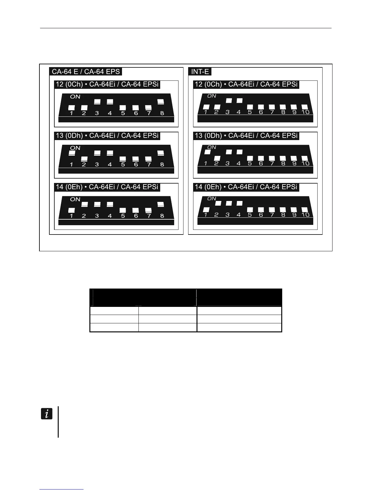
Fig. 16. Setting the DIP-switches in expanders to be identified as CA-64 Ei / CA-64 EPSi.
Table 2 shows numbering of the expander zones depending on the address set. If a number
of expander zone coincides with a number of mainboard zone or a number of wireless zone,
you can select which zone is to be supported (see: PROGRAMMING manual).
Expander address
decimally hexadecimally
Zone numbers
12 0C 7-14
13 0D 15-22
14 0E 23-30
Table 2.
5.5.7 Connecting the hardwired output expander
One INT-O / INT-ORS / CA-64 O / CA-64 OPS expander can be connected to the control
panel. This enables expansion of the system by adding 8 programmable wired outputs.
Address 15 (0Fh) must be set in the expander. In the case of the INT-ORS expander, you
must also use the DIP-switches to define how the expander is to be identified (for detailed
information please refer to the manual delivered with the expander).
The INT-O expander is identified as CA-64 O (the dedicated power supply not
connected to the expander) or CA-64 OPS (the dedicated power supply connected to
the expander).