20 VERSA SATEL
sirens with own power supply (e.g. SP-4002, SP-4004, SP-4006, SP-6500, SPLZ-1011,
SD-3001, SD-6000) – it is recommended to use low-current outputs to trigger the
signaling, and high-current ones – to supply power.
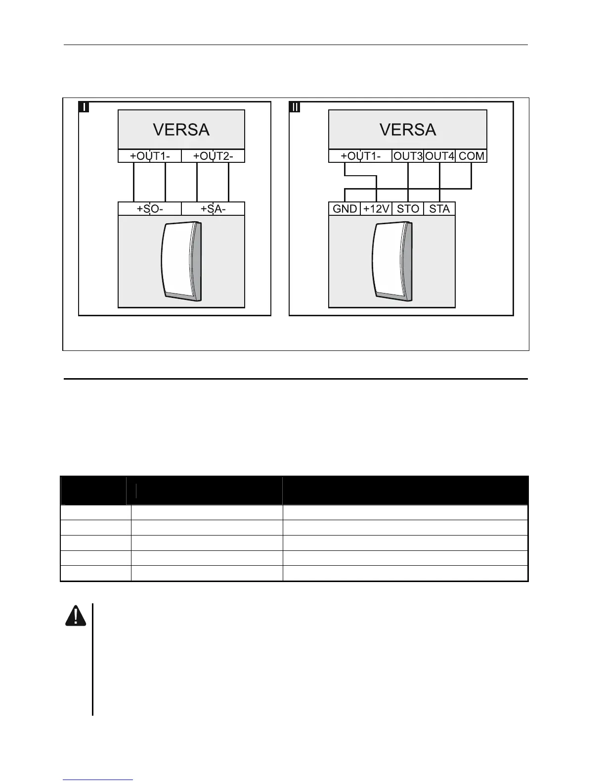
Fig. 23. Connecting sirens to the control panel outputs. I – siren without own power supply.
II - siren with own power supply.
5.8 Connecting the radio monitoring transmitter
The OUT3 and OUT4 outputs of the control panel can be used for control of the NR2-DSC
radio monitoring transmitter (NEMROD system – format PC-16 OUT) manufactured by
NOKTON. In such a case, the SERIAL DATA ON OUT 3/4 global option must be enabled in the
control panel (see PROGRAMMING manual). Table 3 contains description of the connector
contacts in the NOKTON NR2-DSC transmitter, used for connecting to the VERSA control
panel.
Contact
number
Description Connection method
2 alternating voltage check connect to control panel AC terminal
12 power supply connect directly to battery “+” through 2 A fuse
13 common ground connect to control panel COM terminal
14 TAKT connect to control panel OUT3 terminal
15 PGM connect to control panel OUT4 terminal
Table 3.
Never connect the contact 13 (common ground) of the NR2-DSC transmitter
connector to the battery “-”. Connecting the transmitter common ground to the
battery “-” may not only cause quick discharge of the battery, but even damage
to the control panel.
Never connect the contact 13 (common ground) of the NR2-DSC transmitter
connector to the control panel COM terminal and the battery “-”, as it may cause
damage to the control panel.