SATEL VERSA 11
KPD - +12 V DC power output.
CLK - communication bus clock.
DTA - communication bus data.
Z1...Z4 - zones.
TMP - tamper input (NC) – if not used, it should be shorted to the common
ground. The TMP input has number 31 in the system.
- protective terminal of telephone communicator (to be connected only to
the PE protective earth circuit of 230 V AC mains).
T-1, R-1 - telephone line output (telephone set connection).
TIP, RING - telephone line input (analog PSTN line).
5.5 Connecting devices to the communication bus
The bus wires must be run in one cable.
The total length of the expander bus may not exceed 600 m.
The device can be powered directly from the control panel, if the distance to the
control panel does not exceed 300 m. Where the distance is greater, another power
source must be provided for the device (power supply or expander with power supply).
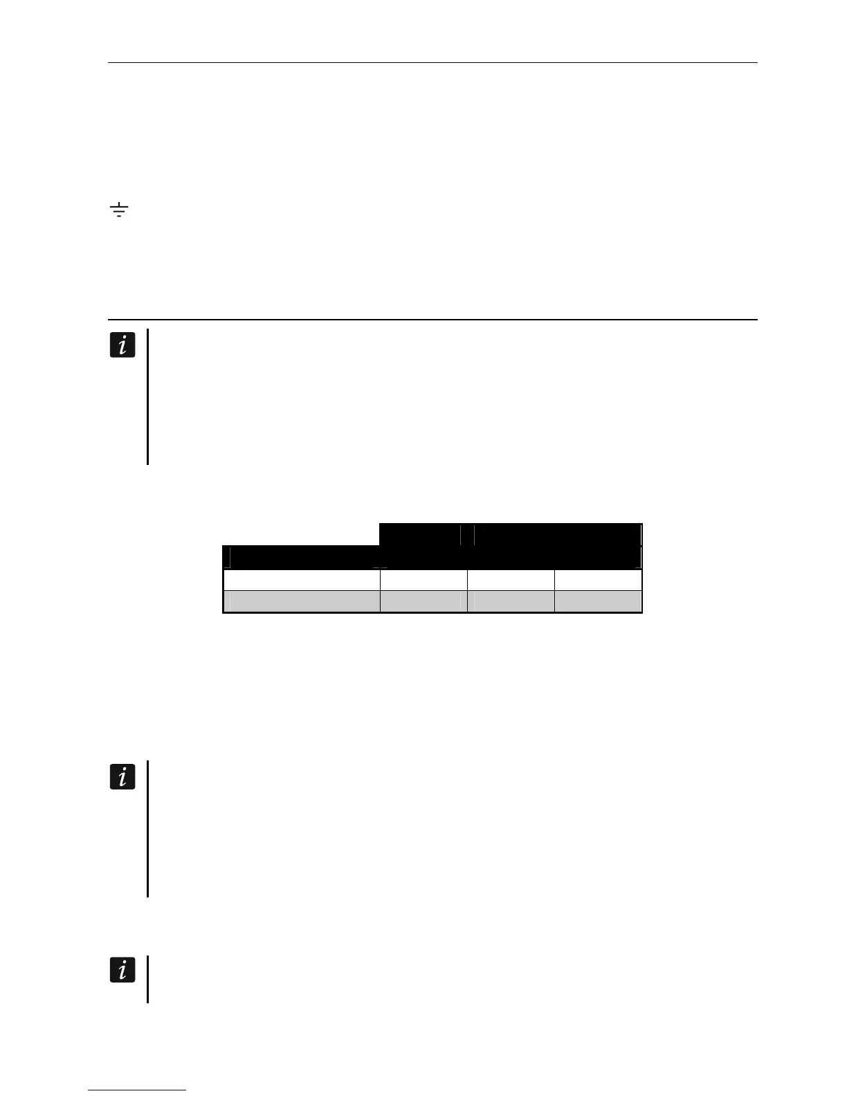
The Table 1 shows the number of wires required for correct connection of the device to the
expander bus if conductors with 0.5 mm diameter are used.
CLK DTA COM
Distance Number of wires
up to 300 m 1 1 1
300-600 m 2 2 2
Table 1.
For most devices to be connected to the communication bus, setting of a suitable address is
required. Two devices must not share the same address (otherwise their identification will be
impossible). For information on the requirements related to address setting, please refer to
the sections describing how specific devices are to connected.
5.5.1 Connecting hardwired keypads
To meet the EN 50131 standard requirements for Grade 2:
keypads with firmware version 1.01 or newer must be connected to the control
panel,
at least one LCD keypad must be connected to the control panel.
This will allow the users to be informed about the system state, as required by the
standard.
The control panel supports up to 6 wired and wireless keypads. Addresses of the keypads
must be set within a range from 0 to 5. Description of programming keypad addresses – see
p. 24.
If the ETHM-1 / ETHM-1 Plus module is connected to the control panel (address 4),
the control panel can support up to 5 keypads.