1
1
2
2
X
X
-
-
M
M
i
i
n
n
d
d
®
®
D
D
C
C
4. ELECTRICAL LINE REQUIREMENTS
a. The electrical line must be "single-phase" type
b. It is essential that a 16A – 250V, magnetothermal differential switch be fitted
upstream of the X-ray system, with differential protection In<= 30mA
(refer to §20 “ATTACHMENTS”)
c. The power cords of the timer and the tubehead connection conductors with must be
two-pole + ground, and in proportion to the length of the power cord, as shown in
Chart 2
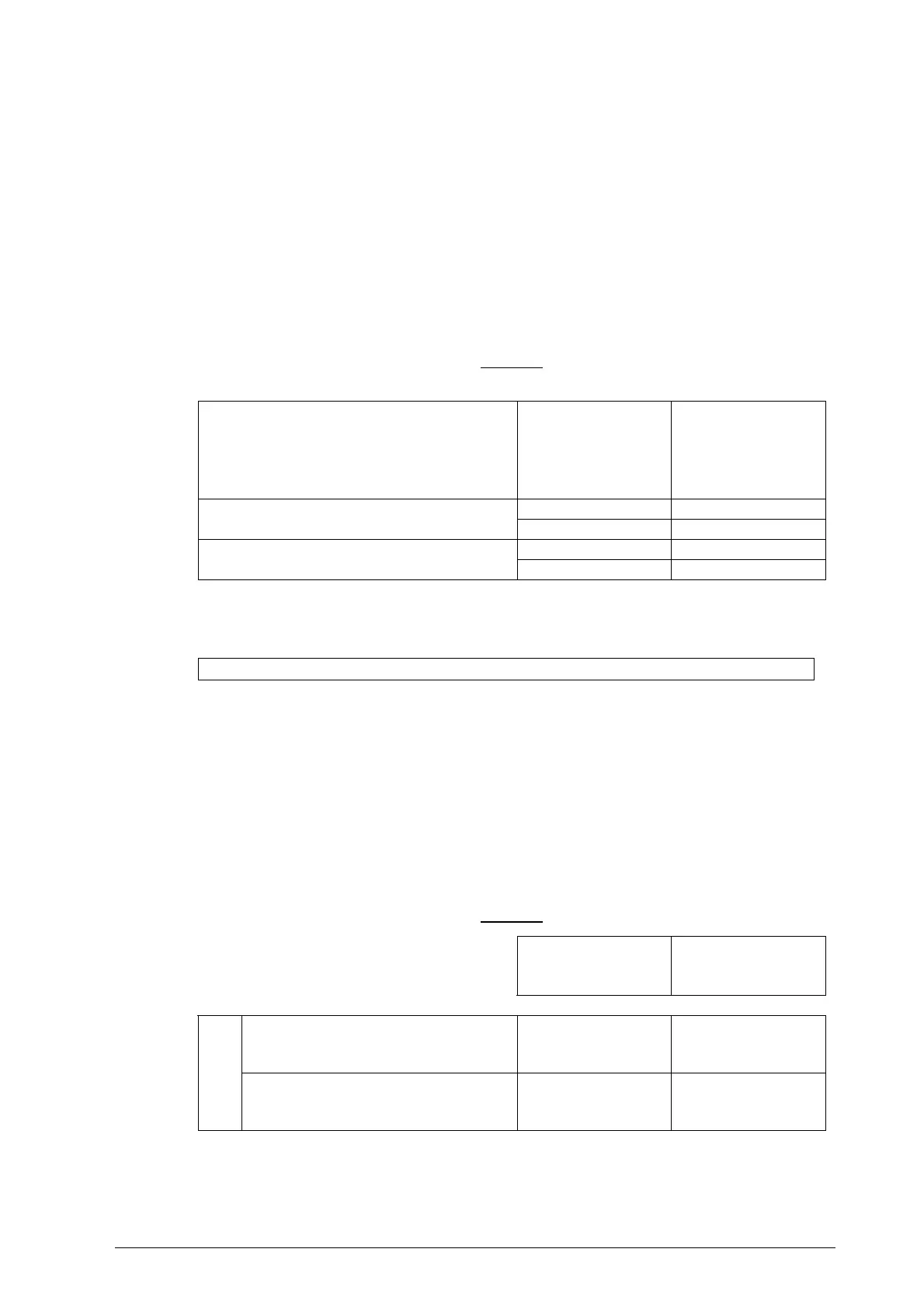
CHART 2
POWER SUPPLY VOLTAGE
MINIMUM
CONDUCTOR
SECTION
MAXIMUM
LINE
LENGTH
1.5 mm
2
10 meters
196V to 264V
2.5 mm
2
20 meters
1.5 mm
2
10 meters
98V to 132V
2.5 mm
2
20 meters
PLEASE NOTE
For longer lines, the cord section must be increased in proportion.
d. The communication cables (C11, C12 – C21, C22) between the timer and X-Ray must
be two-pole, twisted and shielded with >0.25 mm
2
section (example: Belden 9501
type)
e. The cables (S11, S12 – S21, S22) connecting the timer and the signal lamps located
outside the surgery must be two-pole > 0.5 mm
2
f. The electrical line characteristics must comply with Chart 3
CHART 3
LINE VOLTAGE
230 V
± 15%
115 V ± 15%
MAXIMUM LINE VOLTAGE DROP
3% 3%
ELECTRICAL
LINE
MAXIMUM LINE APPARENT RESISTANCE
0.5 ohm 0.5 ohm