PN 9001078
Rev. A
Page 1-7
Section 1. Overview and Specifications
SATO CL408e/CL412e Service Manual
*NOTE: Optional RS232 Communication Card contains DSW1 switches which are
configured when supplied with the printer.
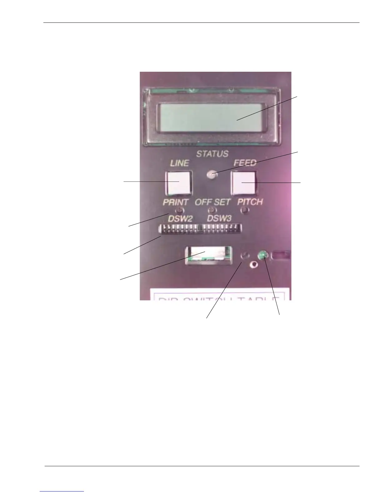
1.5 Operation Panel
LCD DISPLAY
PANEL
TWO-COLOR
STATUS LED
FEED KEY
PRINT/OFFSET/PITCH
POTENTIOMETERS
OPTION
CONNECTIOR
LABEL TAKEN LED
LINE KEY
*DSW2 & 3
LABEL TAKEN THRESHOLD
POTENTIOMETER
The CL408e/CL412e Operator Panel consists of one two-color (red and green) LED
indicator, two momentary contact switches, two DIP switches (a third is located on the
RS232 interface card), four adjustment potentiometers and one LCD display. All of
these are accessible from the front of the printer, however some are not accessible
unless the front cover is open. They are used to set the printer operating parameters
and to indicate the status of the printer to the operator.

 Loading...


