Page 9-17
Section 9. Optional Accessories
SATO CL408e/CL412e Service Manual
PN 9001078
Rev. A
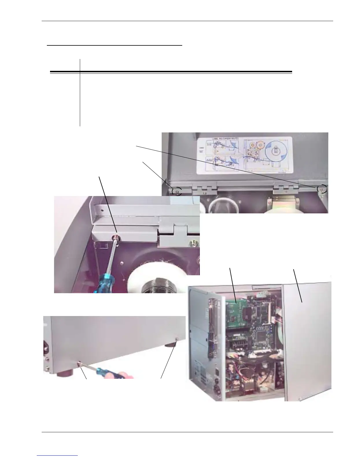
PCMCIA Memory Expansion Installation
RAISE THE TOP ACCESS
DOOR AND REMOVE (2)
SCREWS HOLDING THE SIDE
COVER TO THE FRAME
REMOVE (2) SCREWS
HOLDING THE SIDE COVER
TO THE OUTSIDE FRAME
STEP PROCEDURE
1. Turn the printer OFF and disconnect the AC power cord.
2. Raise the access door and remove (2) screws holding the
electronics side cover to the inside frame. Figs. 9-31
3. Remove (2) screws holding the electronics side cover to the
outside frame. Remove the cover by lifting upwards to expose
the main PCB.
ELECTRONICS
COMPARTMENT
REMOVE SIDE
COVER BY
LIFTING UPWARDS
Removing the Main PCB Board
Figs. 9-31

 Loading...


