20 SawStop 10” Professional Cabinet Saw
Assembling Your Saw
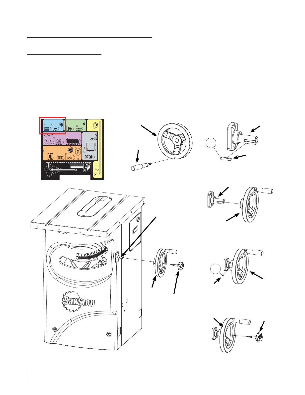
Installing the Tilt Handwheel
3. Open the other handwheel package and screw the handle into the handwheel (see Fig. 13). Tighten the handle
with a 14 mm wrench. The hardware required to install the tilt handwheel is located in the area with the blue
background on the Table Saw Hardware Pack. Remove a key from the Table Saw Hardware Pack and insert it
into the slot at the end of the tilt control shaft (see Fig. 14). Slide the handwheel onto the end of the tilt control
shaft (see Fig. 15) until the face of the handwheel is fl ush with the end of the tilt control shaft. Remove a set
screw from the Table Saw Hardware Pack and insert it into the small hole located on the side of the handwheel
(see Fig. 16). Use a 3 mm hex key to fully tighten the set screw. Locate the lock knob with the shorter shaft.
Screw the lock knob into the end of the tilt control shaft (see Fig. 17), but don’t tighten it completely. The lock
knob is used to prevent the handwheel from turning after the blade has been set to a new tilt angle.
!
WARNING
Do not operate with door open.
The blade can retract and cause
a severe injury if you touch it inside
the cabinet. Also, moving parts can
cut, pinch or crush.
handle
handwheel
1
tilt control
shaft
handwheel
Fig. 13
Fig. 15
key
tilt control
shaft
tilt control
shaft
handwheel
tilt lock
knob
2
set screw
handwheel
Fig. 14
handwheel
tilt lock
knob
Fig. 16
Fig. 18
Fig. 17
Mounting the Switch Box
Hardware for Step 7
Button Head Socket Screws,
M6 x 20 (2)
9
Switch Box
Keys (2)
Installing the Handwheels
Hardware for Steps 2-3
1
Keys,
5 x 5 x 25 (2)
Set Screws,
M6 x 8 (2)
2
Mounting the Dust Port
Hardware for Step 4
Mounting
the
Motor
Cover
Hardware for Step 5
F
Mounting the
Wrench & Tool
Holders
Hardware for Step 8
Motor
Cover
Rod
5
Blade
Wrench
Holder
13
Button Head
Screws,
M6 x 12 (2)
15
Lock
Washers,
M6 (2)
14
12
Mounting the Extension Wings
Hardware for Step 6
Washers,
M8 (8)
6
Hex Bolts, M8 x 16 (8)
8
Lock Washers, M8 (8)
7
Tools
Lock Washers,
M6 (2)
10
Washers, M6 (2)
11
Hex Key, M8 (1)
Blade Spacing
Adjustment Gauge (1)
Hex Keys: M3 (1), M4 (1), M5 (1), M6 (1)
Lock Washers,
M5 (3)
4
Button Head Screws,
M5 x 3 x 15 (3)
3