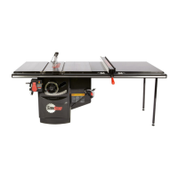
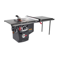
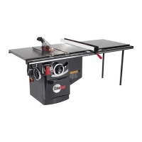
22 SawStop 10” Professional Cabinet Saw
Assembling Your Saw
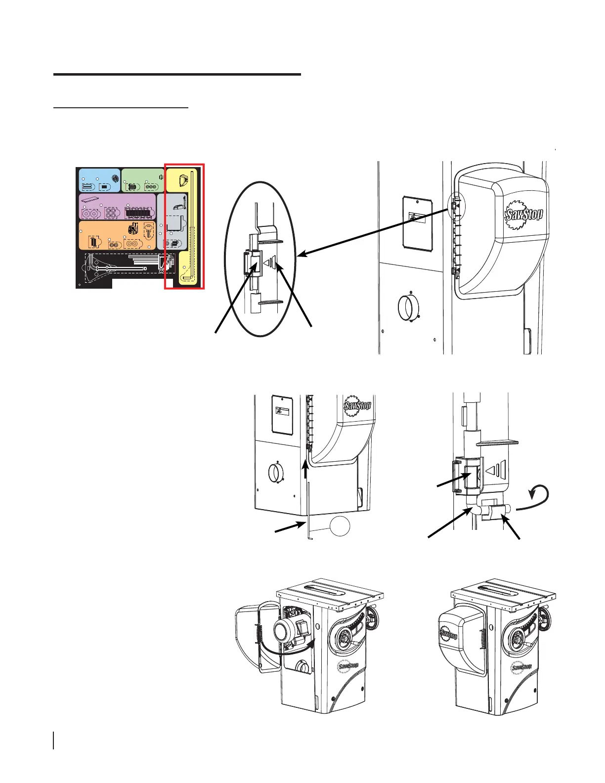
Slip the straight end of the motor
cover rod up through the bottom
tube then through the row of half-
cylinders along the edge of the
motor cover and fi nally through the
upper tube (see Fig. 23). Rotate the
motor cover rod so that the bent end
of the rod fi ts into the hook on the
motor cover just below the bottom
metal tube (see Fig. 24).
To open the motor cover press
on the ribbed section on the
front of the motor cover until it
unlatches and swing the cover
away from the cabinet. Reverse
the process to close the cover
(see Fig. 25).
!
WARNING
Moving gears and parts
can pinch, cut or crush.
Do not operate with
door open.
upper tube
on cabinet
arrow on
motor cover
lower tube
on cabinet
rod
hook on
motor
cover
5
!
WARNING
Moving gears and parts
can pinch, cut or crush.
Do not operate with
door open.
Fig. 22
Installing the Motor Cover
5. Locate the motor cover and remove the motor cover rod from the area with the yellow background on the Table
Saw Hardware Pack. Hold the motor cover against the side of the saw over the motor such that the two arrows
on the side of the cover point to the two metal tubes on the side of the cabinet (see Fig. 22).
Fig. 23 Fig. 24
Fig. 25
rod
Mounting the Switch Box
Hardware for Step 7
Button Head Socket Screws,
M6 x 20 (2)
9
Switch Box
Keys (2)
Installing the Handwheels
Hardware for Steps 2-3
1
Keys,
5 x 5 x 25 (2)
Set Screws,
M6 x 8 (2)
2
Mounting the Dust Port
Hardware for Step 4
Mounting
the
Motor
Cover
Hardware for Step 5
F
Mounting the
Wrench & Tool
Holders
Hardware for Step 8
Motor
Cover
Rod
5
Blade
Wrench
Holder
13
Button Head
Screws,
M6 x 12 (2)
15
Lock
Washers,
M6 (2)
14
12
Mounting the Extension Wings
Hardware for Step 6
Washers,
M8 (8)
6
Hex Bolts, M8 x 16 (8)
8
Lock Washers, M8 (8)
7
Tools
Lock Washers,
M6 (2)
10
Washers, M6 (2)
11
Hex Key, M8 (1)
Blade Spacing
Adjustment Gauge (1)
Hex Keys: M3 (1), M4 (1), M5 (1), M6 (1)
Lock Washers,
M5 (3)
4
Button Head Screws,
M5 x 3 x 15 (3)
3