EasyManuals Logo

Scania DI13 series User Manual

Scania DI13 series
74 pages
To Next Page IconTo Next Page
To Previous Page IconTo Previous Page
Page #14 background imageLoading...
Page #14 background image
OPM 250 en-GB 14
©
Scania CV AB 2016, Sweden
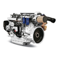
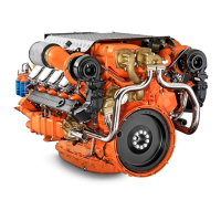
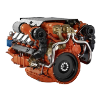
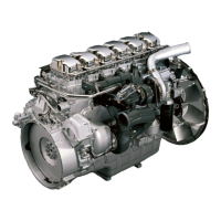
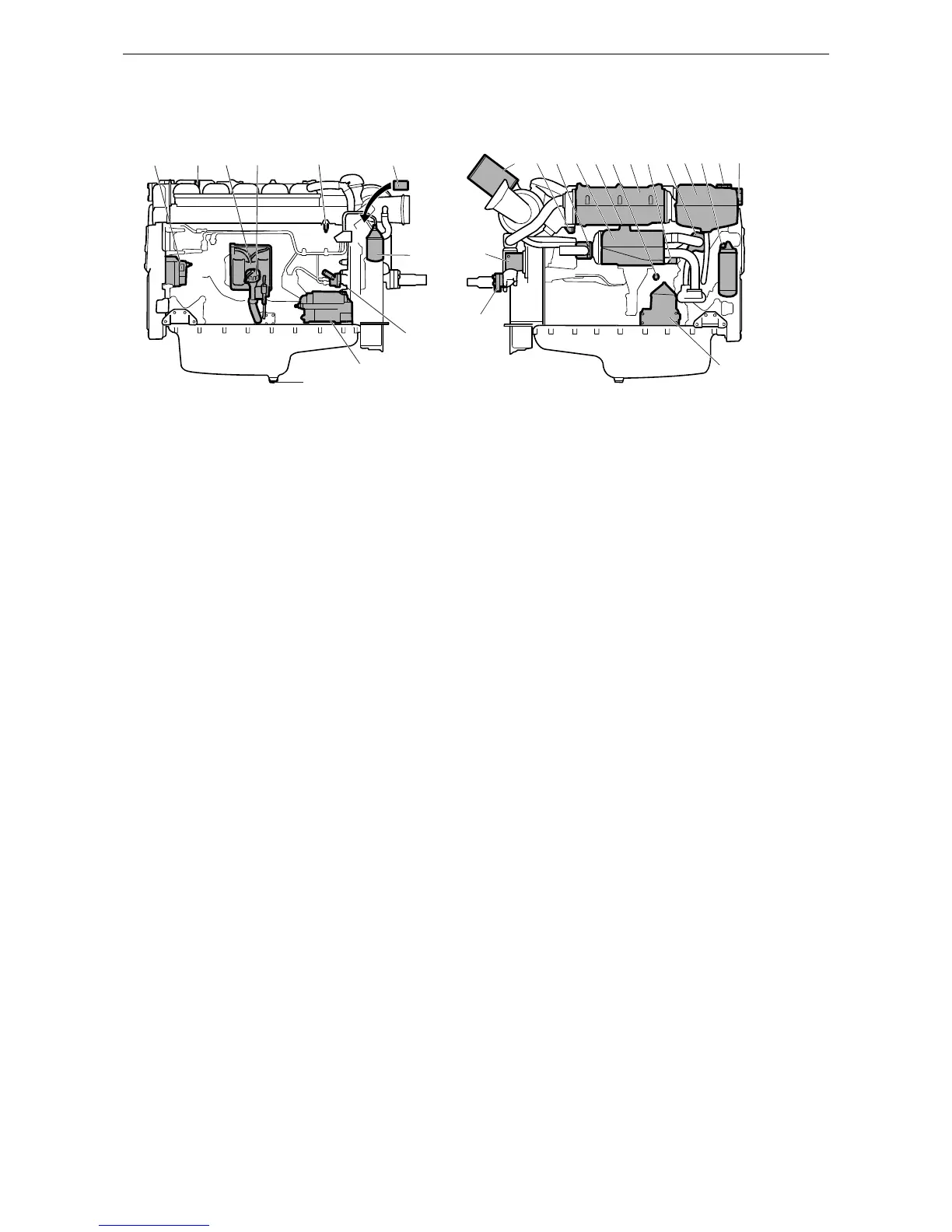
Component identification
1. Alternator
2. Oil filler cap
3. Engine control unit
4. Oil dipstick
5. Fuel manifold bleed nipple
6. Engine data plate
7. Fuel filter
8. Fuel pump with hand pump
9. Starter motor
10. Oil plug
11. Air filter
12. Sacrificial anodes (2)
13. Sea water outlet
14. Heat exchanger
15. Holes for draining condensation in charge air cooler
16. Valve for draining coolant
17. Charge air cooler
18. Thermostat
19. Expansion tank
20. Oil filter
21. Filling coolant
22. Level glass for checking coolant level
23. Centrifugal oil cleaner
24. Sea water intake
25. Sea water pump
1
5
6
12
11
7
8
10
9
2
13
14
25
24
23
15 16
17
12
18
19 20
21
22
3
4
343 190
The illustration shows a normal version of a DI13 engine with heat exchanger. The engine ordered may have
different equipment.

Table of Contents

Questions and Answers:

Question and Answer IconNeed help?

Do you have a question about the Scania DI13 series and is the answer not in the manual?

Scania DI13 series Specifications

General IconGeneral
Cooling SystemLiquid-cooled
Displacement12.7 liters
AspirationTurbocharged
AftertreatmentSCR (Selective Catalytic Reduction)
Engine TypeInline 6-cylinder
Fuel SystemCommon rail direct injection

Related product manuals