en
7/
Control System and Electric System (PX 105)FIT--Wa 1159850Dec./06
48
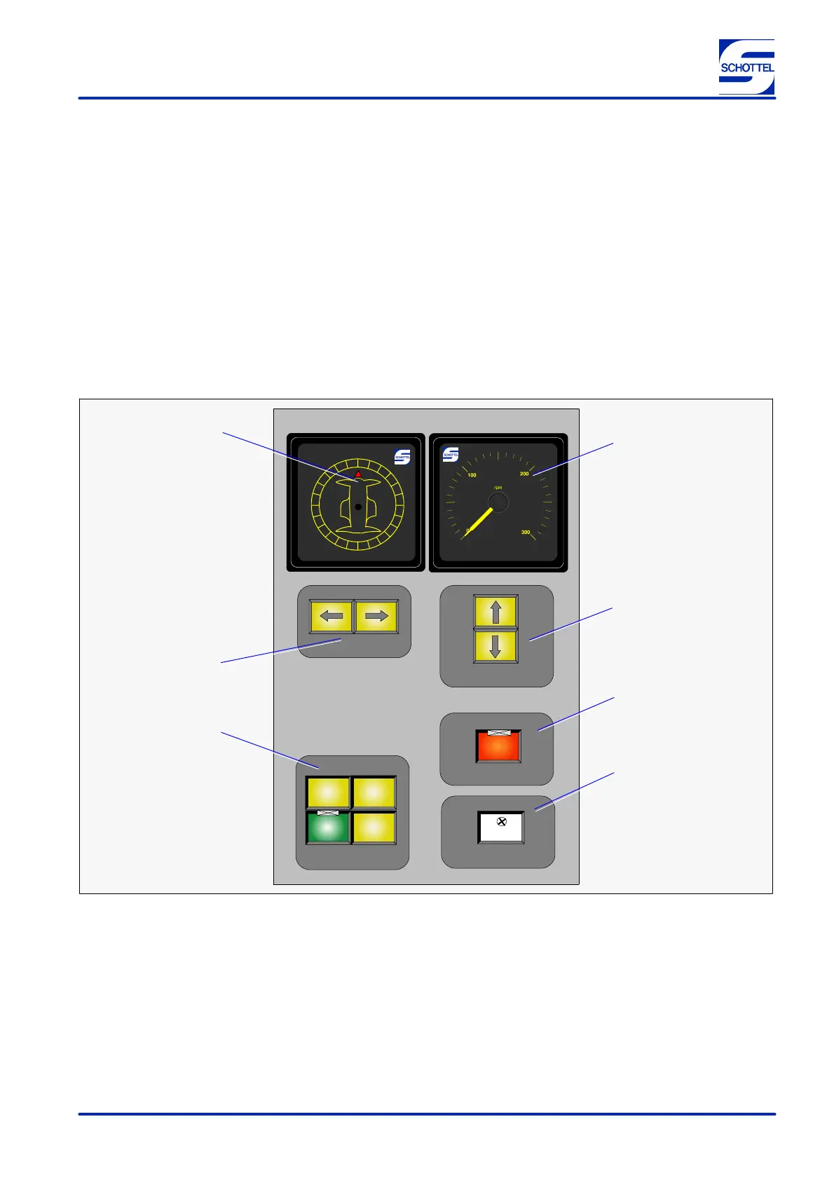
Local control stand
The arrangement of the operating and display elements of both local control stands is identical.
The following operating and display elements are arranged on the local control stand:
D Thrust direction indicator (4/1)
D Speed indication (4/2)
D Display and control field ”SPEED” (4/3)
D Display and control field ”EMERGENCY STOP”
(4/4)
D Display and control field ”LAMPS” (4/5)
D Display and control field ”DESK SELECTION”
(4/6)
D Display and control field ”STEERING” (4/7)
6
2
SPEED
EMERGENCY STOP
3
4
5
1
STEERING
STOP
7
EMERG
TEST
LAMPS
LOCAL
BRIDGE
IN SERVICE
CONTROL
SEND
COMMAND
ECR DESK
IN SERVICE
DESK SELECTION
Figure 4
 Loading...