en
3/
Piping Systems for Hydraulic, Lubrication and Similar SystemsSTD--Wa 07/3110 1099237 17
1 Conduits
General
For the conduits only the material listed in the according
hydraulic circuit diagram is allowed to be used.
Threaded joints unconditionally have to consist of the
same material as the conduits.
The pipe cross sections stated in the diagrams of com-
pany SCHOTTEL are to be met as minimum values.
For placing the shortest possible connections are to be
chosen and bends are to be avoided.
For bending a bending radius of at least 3 times the pipe
diameter is to be observed.
As supports for the conduits slightly damping or flexibly
bedded fastening elements have to be used because
of the noise generation.
During this procedure attention is to be paid to a solid
fastenings of not too much distance to prevent vibra-
tions of the conduits and thus unnecessary noise.
For avoiding tensions it is required to preview expan-
sion bends. The connecting pipes are to be placed such
that no air cushions can generate.
Vent lines are to be placed continuously ascending.
!
ATTENTION
While handling the pipes, the separating cut of the
manufacturer is to be cut by approx. 10 mm.
(Source of error attributable to supply).
NOTE
After bending, cutting and mounting the final layout, we
recommend a pressure test for all conduits applying a
test pressure of 1.5 x operating pressure.
Cold bending of pipes
Cold bending is only allowed with the according pipe
bending device such that there is no contraction of the
cross section.
!
ATTENTION
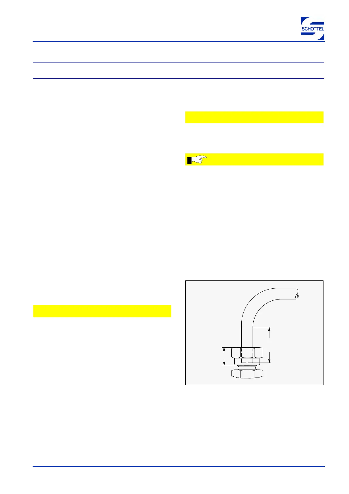
Prior to bending it is required to pay attention that the
tail end of the pipe protruding into the joint shall have a
minimum length of 2 time the nut height, see Figure 1.
For pipes with a Ø of 6 to approx. 25 mm (depending on
the wall thickness) manual bending devices are avail-
able.
For larger diameters and wall thickness machine equip-
ment is to be used.
2H
H
Figure 1