Betriebs--, Montage-- und Wartungsanleitungen 1099230
Operating--, Mounting-- and Maintenance Instructions
GB
Edition
K D -- G E -- g e
Ausgabe /
983/00
D/
5/25
SRP 1212
1 Technische Beschreibung
1.1 Allgemeines
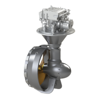
Der als Z--Antrieb ausgelegte SRP besteht aus den
drei Hauptgruppen:
Oberwassergetriebe (1) mit Schmierölaus-
gleichsbehälter (4)
Schaft (13) mit Tragrohr (11)
Unterwassergetriebe (18) mit dem Propeller
(19).
Zum Korrosionsschutz sind neben dem m ehr-
schichtigen Unterwasseranstrich noch Anoden
(17) angebracht. Die Kraftübertragung erfolgt vom
Antriebsflansch (6) über die An triebswelle (5) auf
ein spiralverzahntesKegelradpaar (7). Von dortaus
wird die Antriebskraft über die Kraftübertragungs-
welle (12), das Kegelradpaar (14) und die Propel-
lerwelle (15) auf den Propeller (19) weitergeleitet.
Die Kegelräder sind einsatzgehärtet und geschlif-
fen.
1.2 Steuerung
Das Unterwassergetriebe (18) mit dem Propeller
(19) kann über die Hydraulik--Ölmotoren (24), die
Steuerungs--Planetengetriebe (23) und das Steue-
rungs--Stirnradgetriebe (8) endlos nach ”Bb” oder
”Stb” gedreht werden, so daß der Propellerschub in
jede gewünschte Richtung gebracht werden kann.
Damit wird die optimale Kombination von Antrieb
und Steuerung erreicht.
Technical description
General
The SRP designed in the form of a Z --drive con-
sists of the following three main assemblies:
Upper g ear--box (1) including lubricating oil
header tank (4)
Shaft (13) with support tube (11)
Lower gear--box (18) including propeller
(19).
Apart from a multi--coat of underwater painting
anodes (17) are attached to the SRP to protect the
system against corrosion. Power is transmitted
from the drive flange (6) via the driving shaft (5)
to a spirallygrooved bevel gear set (7). From there
the pow er is transmitted via the transmission sh aft
(12), the bevel gear set (14) and the propeller shaft
(15) to the propeller (19). The bevel gears are ca-
se--hardened and grounded.
Steering
The lower gear--box (18) with the propeller (19)
can infinitely be turned to p ort or starboard by
means of the hydraulic oil motors (24), the steer-
ing p lanetary gearings (23) and the steering spur
gear (8); thus, the propeller thrust can be routed to
any direction desired.
As a result, the best combination of p ropulsion
and steering is achieved.