02.00 | KSP3, KSP3-LH, KSP3-F | Assembly and Operating Manual | en |
1463318
5.3.1 Supply lines
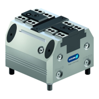
The clamping force block has four air connections: I, II, III, IV.
Two connections for OPEN (I and III) and two connections for
CLOSE (II and IV).
Which of the two air connections has to be opened for actuation
depends on the application:
• Connections I and II for operation without a base plate.
• Connections III and IV in the base for hose-free direct
connection to the machine table or on the base plate.
The threads for hose-free, direct connection are not designed for
pneumatic fittings.
Thread for pneumatic fitting (frontal):
KSP3, KSP3-LH, KSP3-F 64 und 100
KSP3, KSP3-LH, KSP3-F 140, 160 und 250
NOTE:
M5
G1/8"
All four air connections come sealed on delivery of the clamping
force block. On the base side with set-screws (item 60) and on the
front with locking screws (item 23).
•
When using the air purge via connection 5, the two sound
absorbers (V) must be removed and replaced by set-screws (item
93).Accessory kit [
/
38]
Requirements for compressed air supply: compressed air,
compressed air quality according to ISO 8573-1: 7:4:4
Unconditioned compressed air contains dust and oil particles and
moisture, all of which can lead to malfunctions or premature wear
in the clamping force block. The oiler should be no more than 2
meters from the coupling point.
The clamping force block has two more base connections (6/7) for
direct lubrication through the machine table. These connections
come sealed on delivery with set-screws (item 62).
5.3.2 Dynamic pressure monitoring of the jaw end positions (variant
"PM")
Dynamic pressure monitoring for the jaw end positions is
integrated via connections 1 and 4 on the bottom.
Connection 1 → monitoring open jaw position.
Connection 4 → monitoring closed jaw position.
The max. pressure for the monitoring functions is 2 bar.
Limit volumetric flow to 10 l/min.
Pressure difference between stroke end positions min. 1 bar.