02.00 | KSP3, KSP3-LH, KSP3-F | Assembly and Operating Manual | en |
1463318
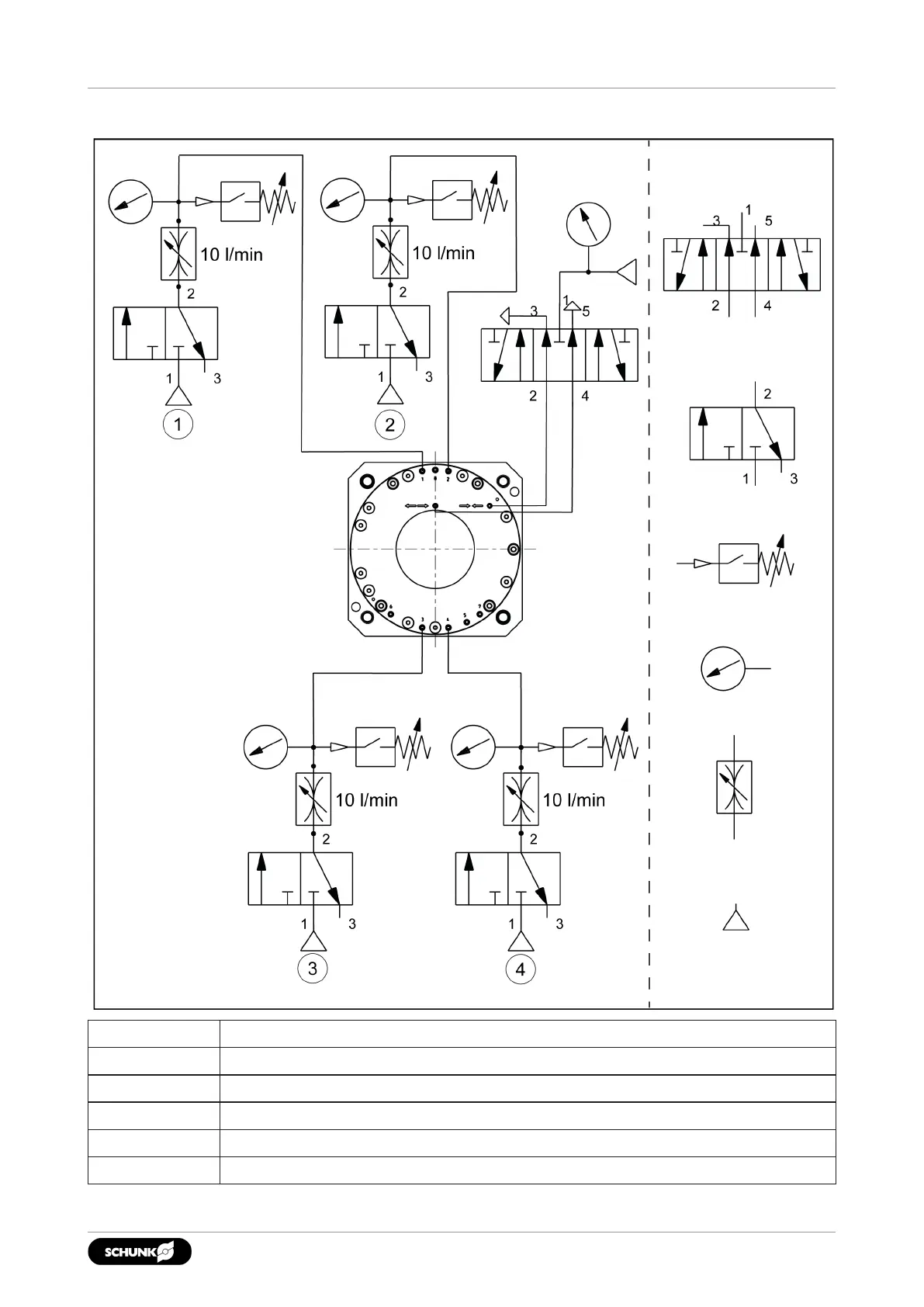
5.3.4 Pneumatic circuit diagram
Circuit symbols
Actuation
5/3 directional control valve, center position ventilated
3/2 directional control valve
Pressure switch
Pressure gauge
Flow control valve
Compressed air supply
Dynamic pressure monitoring for jaw end position "open" (2 bar)
Air coupling in top jaw 1
Air coupling in top jaw 2
Dynamic pressure monitoring jaw stroke "closed" (2 bar)