Assembly and settings
28 03.00 | OSE | Assembly and Operating Manual | en | 1373804
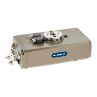
4.4.2 OSE 22-57
Adjustment of the end positions 0° and 180° for variant A and C
1. Set connection A under pressure until product unit reaches its
end position.
2. Loosen the counter-nut (72) at B and adjust the end position
with the stop screw (5).
3. Fasten counter-nut (72) and check end position.
4. Repeat same procedure for 2nd end position.
Adjustment of the end positions at variant B
1. Actuate connection A until the produkt reaches its end
position.
2. Reduce pressure to max. 1 bar.
3. Loosen the counter-nut (72) of the shock absorber’s stop
spindel (31) at A and turn it out as far as possible.
4. Loosen the safety screw (9) at B and adjust the end position of
the adjustment screw (8).
5. Tighten the safety screw (9) and control the end position.
6. Turn the stop screw (31) to the inside until it contacts the piston
(2).
7. Turn the stop screw from this position half a rotation back and
thighten the counter-nut (72).
8. Repeat same procedure for 2nd end position.
Adjustment of the 90° intermediate position at variant C
1. Loosen the counter-nut (item 73) and turn back the stop
spindle slightly (item 13).
✓ The pinion has clearance in the intermediate position.
2. Set connection A under pressure until product unit reaches its
end position.
3. Actuate the connection for the intermediate position.
4. Adjust the intermediate position by means of the stop spindle
(13) at A and thighten the counter-nut (73).
5. Control the adjustment by actuating connection A first and
then the connection of the intermediate position as long as the
produkt needs to arrive its end position.
6. Repeat same procedure for intermediate position B.
7. After adjustment, the pinion must not have any more
clearance in the intermediate position.
NOTE
If the counter-nut is loose (73), air may stream out of the
actuation spindle (13). This is due to the design and normal.