Assembly and settings
4.6.2 Assemble the inductiv proximity switch (IN)
CAUTION
Sensor can be damaged during assembly.
Do not exceed the maximum tightening torque of 100 Ncm for
the set screws.
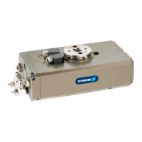
4.6.2.1 OSE 14
1. Insert the sensors into the milled pockets on the upper side of
the housing and secured with the locking screw (66).
2. Loosen the thread pin (23-3) on the switching cam (23) by 1/2
turn, so that the cam can be moved.
3. Actuate connection A until the product has reached its end
position.
4. Move the switching cam until the sensor at B is actuated
5. Fasten the thread pin (23-3)
Repeat same procedure for the 2nd end / intermediate position.
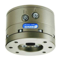
4.6.2.2 OSE 22 - 40
variant A and B:
1. Adjust the quick action bushing (21a) in a way that the passing
control cams have a distance of 0.5 mm.
2. Slightly clamp the bushing with a set-screw (21b).
3. For being able to move the cam, loosen the set-screw at the
control cam (23) appr. by half a rotation.
4. Actuate connection A until theproduct arrives at its end
position.
5. Move the switching cam until the sensor at B is actuated
6. Turn the pinion out of this position and thighten the set-screw
at the control cam.
Adjustment of the other end position is done the same way.
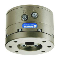
variant C:
1. Mount the control cam in the groove, which emerges from the
unscrewing of the clamping disk C (19 or 18) at the pinion.
2. The sensor is supported by the clamping pieces (22) during
monitoring of the intermediate position.
3. Adjust the sensor in a way that the passing control cams have a
distance of 0.5 mm
4. Clamp the sensor with the screw (75).
3303.00 | OSE | Assembly and Operating Manual | en | 1373804