Assembly and settings
32 03.00 | OSE | Assembly and Operating Manual | en | 1373804
To disassemble, reverse the sequence described the above.
cable
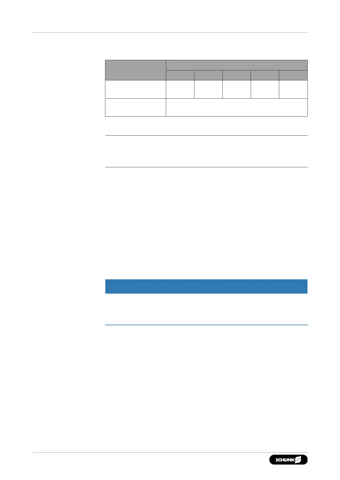
Cable connection, rotating mounting plate
Designation
OSE
22 34 40 45 57
Plug connector for
sensor connection
4 x M8 4 x M12 4 x M12 8 x M12 8 x M12
Bending radius Optimum bending radius for continuous
movement: 10 x cable diameter
4.6 Mounting the sensor
NOTE
Observe the assembly and operating manual of the sensor for
mounting and connecting.
The product is equipped for the use of sensors.
• For the exact type designations of suitable sensors, please see
the catalog data sheet.
• For technical data for the suitable sensors, see Assembly and
Operating Manual and catalog data sheet.
– The Assembly and Operating Manual and catalog data sheet
are included in the scope of delivery for the sensors and are
available at schunk.com.
• Information on handling sensors is available at schunk.com or
from SCHUNK contact persons.
4.6.1 Assemble the magnetic switch (MMS) OSE 63
CAUTION
Risk of damage to the sensor during assembly!
• Observe a maximum tightening torque of 0.2 Ncm for the set-
screws.
1. Actuate a connection until the product has reached one of its
end positions.
2. Insert the sensor into the groove.
3. Position the sensor so that the normally open contact
responds and the sensor switches.
4. Fix the sensor by tightening the grub screw.
5. Swivel the product into the other end position by actuating the
second connection.
6. Proceed in the same way with the second sensor.