Design and description
12.00 | SWS | Assembly and Operating Manual | en | 389456
21
4.1.1 Functional principle
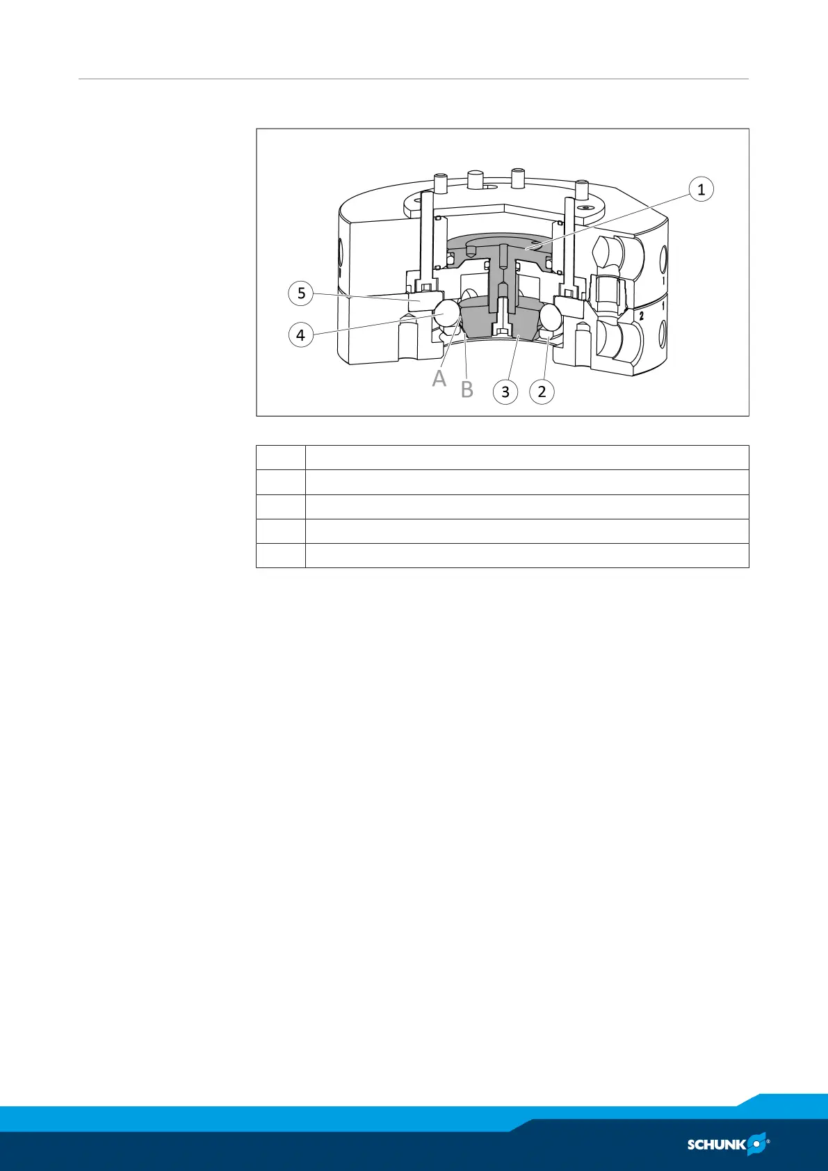
Schematic diagram of locking mechanism
1 Locking piston
2 Male coupling
3 Cam
4 Locking ball
5 Bearing race
Locking
The cam(3) is attached to the locking piston(1) and has two
bevels. When the locking piston(1) is actuated, the cam(3) with
the bevelA presses the locking balls(4) under the hardened
bearing race(5). This presses SWK and SWA together. In the
locked state, the locking balls are between the male coupling(2)
and the inclineB of the cam(3). The bevelB (fail-safe reverse
taper) causes a high locking force. Therefore, separation of SWK
and SWA in the self-locking state is only possible by pneumatic or
manual actuation of the locking piston.
Unlocking
If the locking piston is actuated again, the cam(3) moves in the
opposite direction. The locking balls(4) release from the hardened
bearing race(5). The SWK is in the unlocked state and the SWA can
be separated from the SWK.