- 11 -
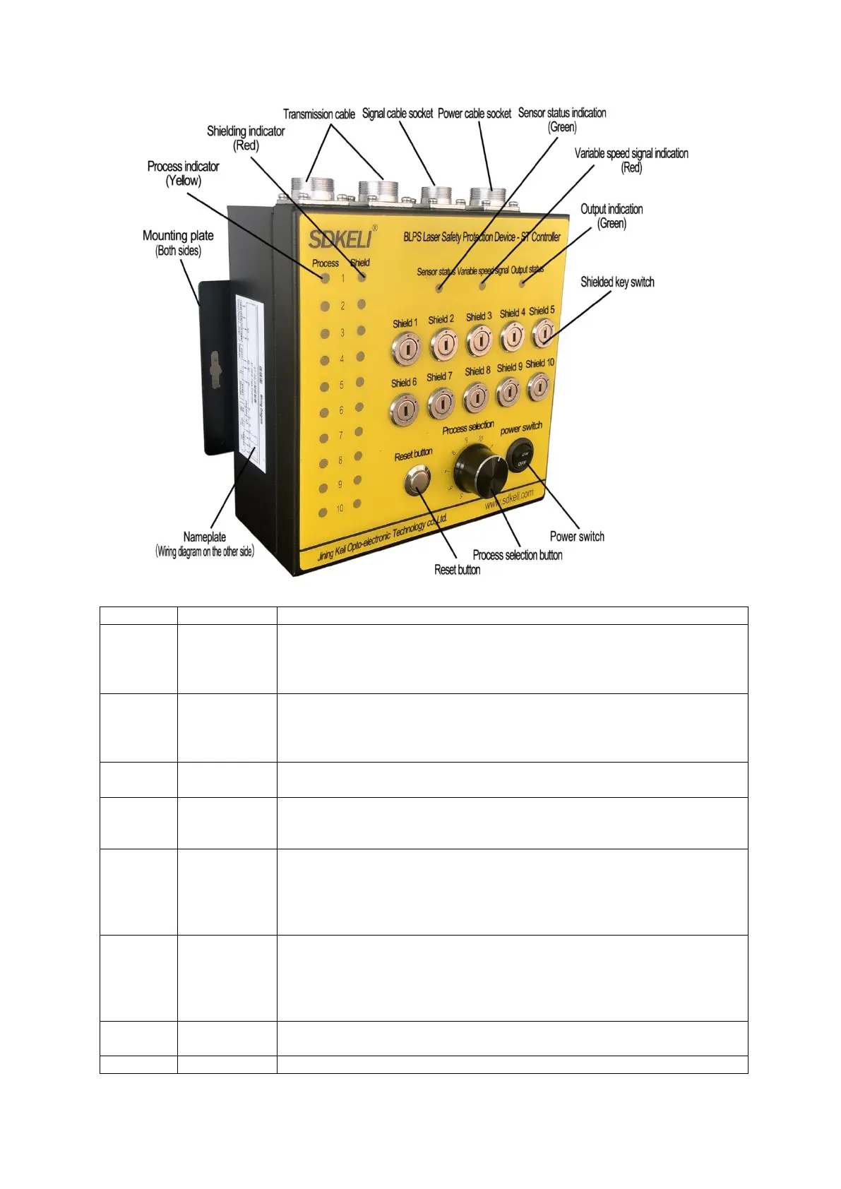
Fig.1.7 Appearance of ST controller
10 yellow indicator lights indicate the current program number. There are 10
processes in total. When the controller status is in a certain process, the
yellow indicator light of this process is on, and the other process lights are
off.
10 red indicator lights, indicating the shielding status of the corresponding
process.The red light is on, indicating that the corresponding process is in
the shielding state;The red light is off, indicating that the corresponding
process is in the normal protection state.
10 two-position key switches are used to select the shielding/normal
function of the corresponding process.
Green indicator light;
The green light is on, the sensor is normal;
The green light is off, and the sensor is shading.
Red indicator light;
The red light is on, the variable speed signal is in the high-level active state,
and the bending machine is in the work advance (slow speed) state at this
time;
The red light is off, and the variable speed signal is in a low level state.
Green indicator light;
The green light is on, and the controller relay contact output is in the closed
state;
The green light is off, and the controller relay contact output is in the
disconnected state.
The self-reset button, when pressed, forces the controller to return to the
process 1 state.
System power control switch