- 37 -
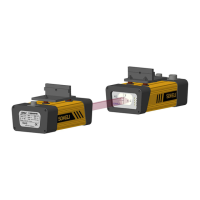
Fig 3.12 Schematic diagram of beam alignment
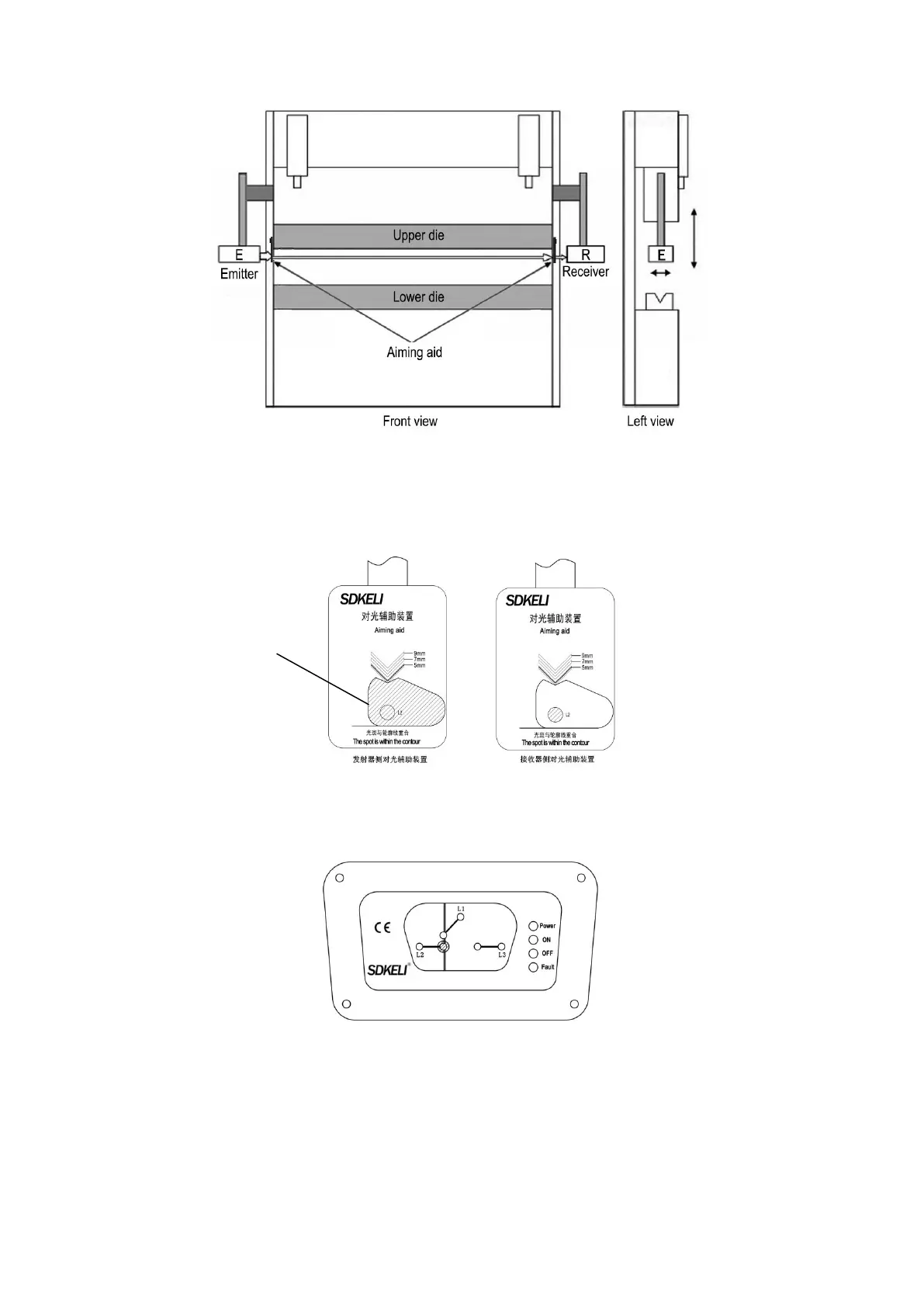
Adjust the transmitter so that the spot is within the spot-shaped contour line on the aiming aid
(transmitter side). Adjust the pitch and left and right angles of the transmitter so that the light
spot passes through the L2 hole on the transmitter side 000, and at the same time passes
through the L2 hole on the receiver side aiming aid.
Fig.3.13 Schematic diagram of light adjustment
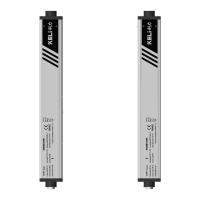
Adjust the receiver, and place the light spot passing through the L2 hole of the aiming aid on
the receiver side on the receiving hole of the receiver L2 to complete the light alignment.
Fig. 3.14 Schematic diagram of receiver window alignment
3.3 Installation of controller
3.3.1 Installation of SR/SP controller
The SR/SP controller is usually mounted on the front side of the upper die slider to be
convenient for workers to operate, using two M6 × 12 screws to fix.