- 39 -
Stop dog should be mounted on the rear area of both sides of the slider and mounting plate
should be mounted on the both sides of the bender. Set the muting point by adjusting the
relative position of limit switch (or approach switch), the stop dog and the mounting plate.
For the related content, seL3.1.2.
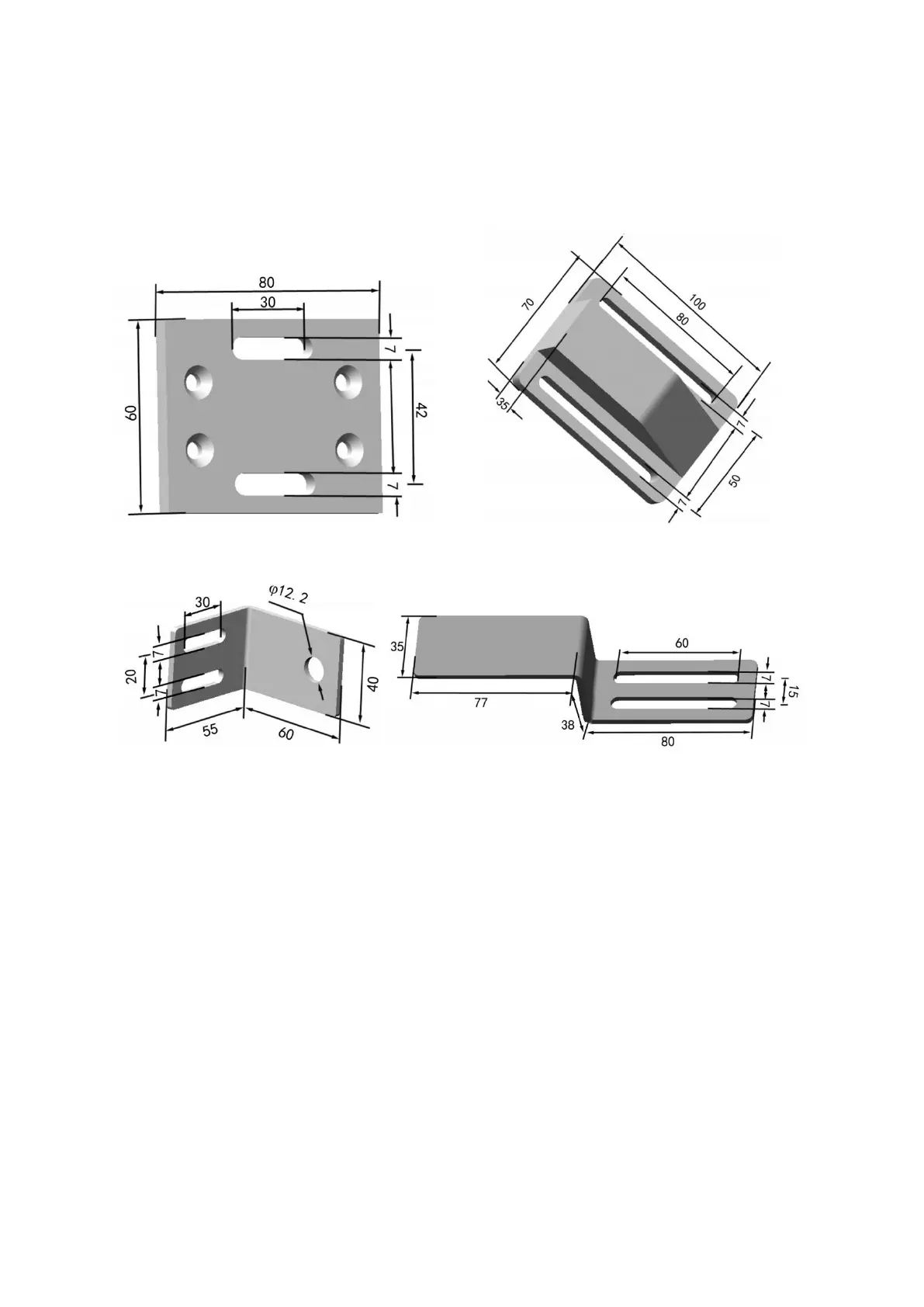
3.4.1 Limit switch
Fig.3.17 Mounting plate of limit switch Fig.3.18 Stop dog of limit switch
3.4.2 Approach switch
Fig.3.19 Mounting plate of approach switch Fig.3.20 Stop dog of approach switch
3.5 Wiring
3.5.1 Wiring considerations
Wiring must be carried out in the case of power cutoff.
Double insulation or reinforced insulation must be used between all the input/output and dangerous
voltage, otherwise it may result in electric shock.
Avoid short circuit between OSSD and the power.
The 0V and shield layer must be connected together to the ground.
All the signal cables of BLPS should not be connected to the DC power source whose output voltage
is higher than 28.8V, or connected to AC power source, otherwise, it may result in electric shock and
damaging the laser safety protection device.
The working voltage of BLPS should not exceed the rated working voltage range, otherwise the
system is not stable.
The wiring should be carried out after the signal identifier has been confirmed.
The cables should be far away from the high-voltage wires, or be placed in the special trunking.