- 35 -
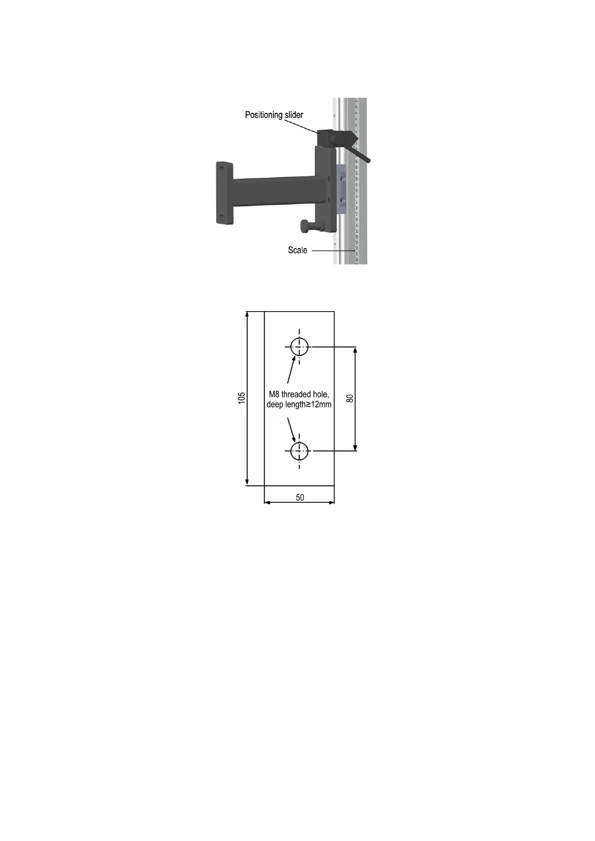
Vertical adjustment structure
Fig.3.8 Vertical adjustment structure
Mounting hole dimensions
Fig.3.9 Mounting hole dimensions
3.2.3 Installation steps
1
)
Select proper position on both sides of the bender slider, machine tool, drill and tap
according to dimensions shown in Fig.3.10. Fix the horizontal bracket
①
onto the slider by
M8×25 inner hexagon screws.
2)The position adjustment handle ② (with elastic cushion) is used in conjunction with the
fast adjustment and limit block, and it is fixed in the vertical bracket
③
rail groove to realize
the fixed position of the rail bracket after sliding up and down.
3 ) Use M6×20 hexagon socket head screws (with spring washers) to fix the slider on the
vertical bracket ③ to realize the connection between the horizontal bracket and the vertical
bracket.
4
)
Fix the vertical support bracket
④
and the adjustment seat
⑤
on the sensor with M6
T-bolts and hexagon nuts (with bullets, flat washers) to realize the connection between the
sensor and the vertical bracket.
5)After the wiring and light adjustment are completed, tighten all the mounting screws.