- 19 -
Section2 Function introduction
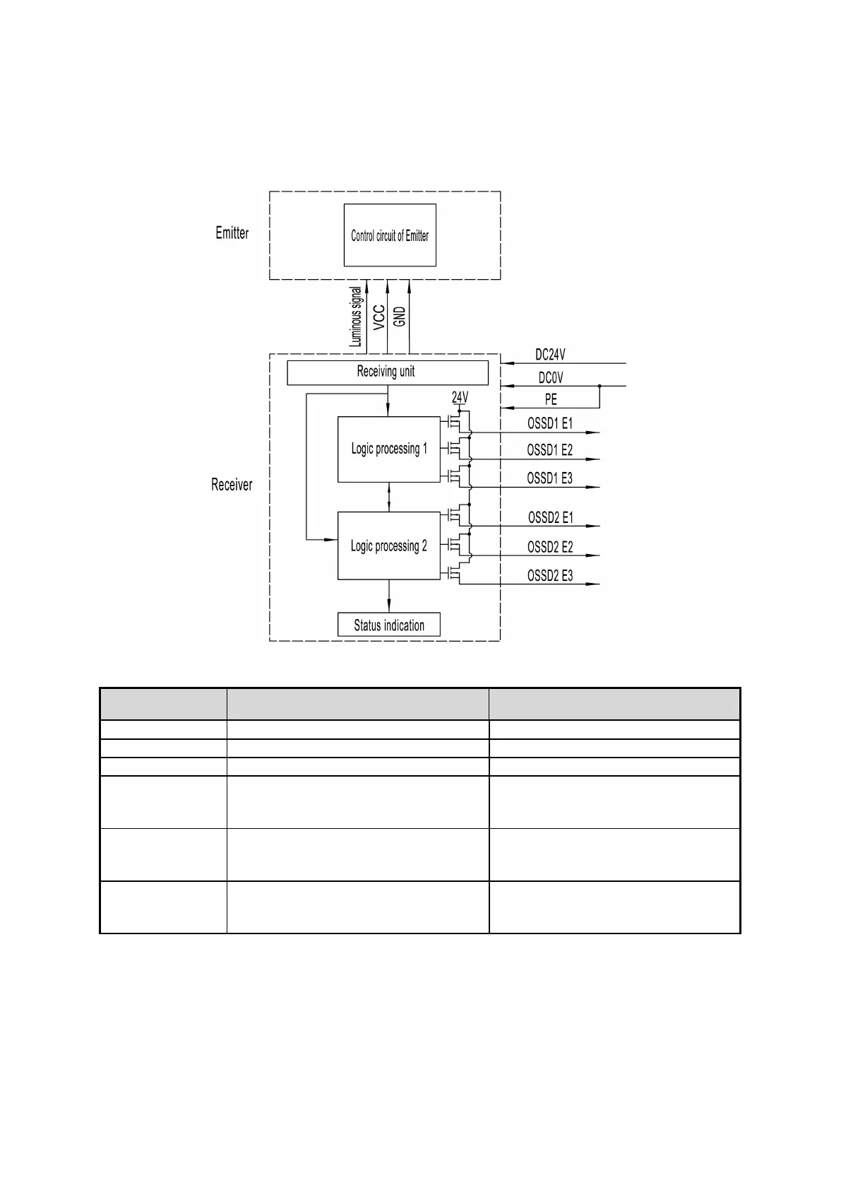
2.1 Input/Output interface circuit
2.1.1 Interface circuit of sensor
Fig.2.1 Interface circuit of sensor
Signal and wiring introduction:
Connect with anode of power supply
Connect with cathode of power supply
Control output interface of L1, PNP
output, output high level voltage when
the sensor is on light-passing state
Control output interface of L2, PNP
output, output high level voltage when
the sensor is on light-passing state
Control output interface of L3, PNP
output, output high level voltage when
the sensor is on light-passing state