- 22 -
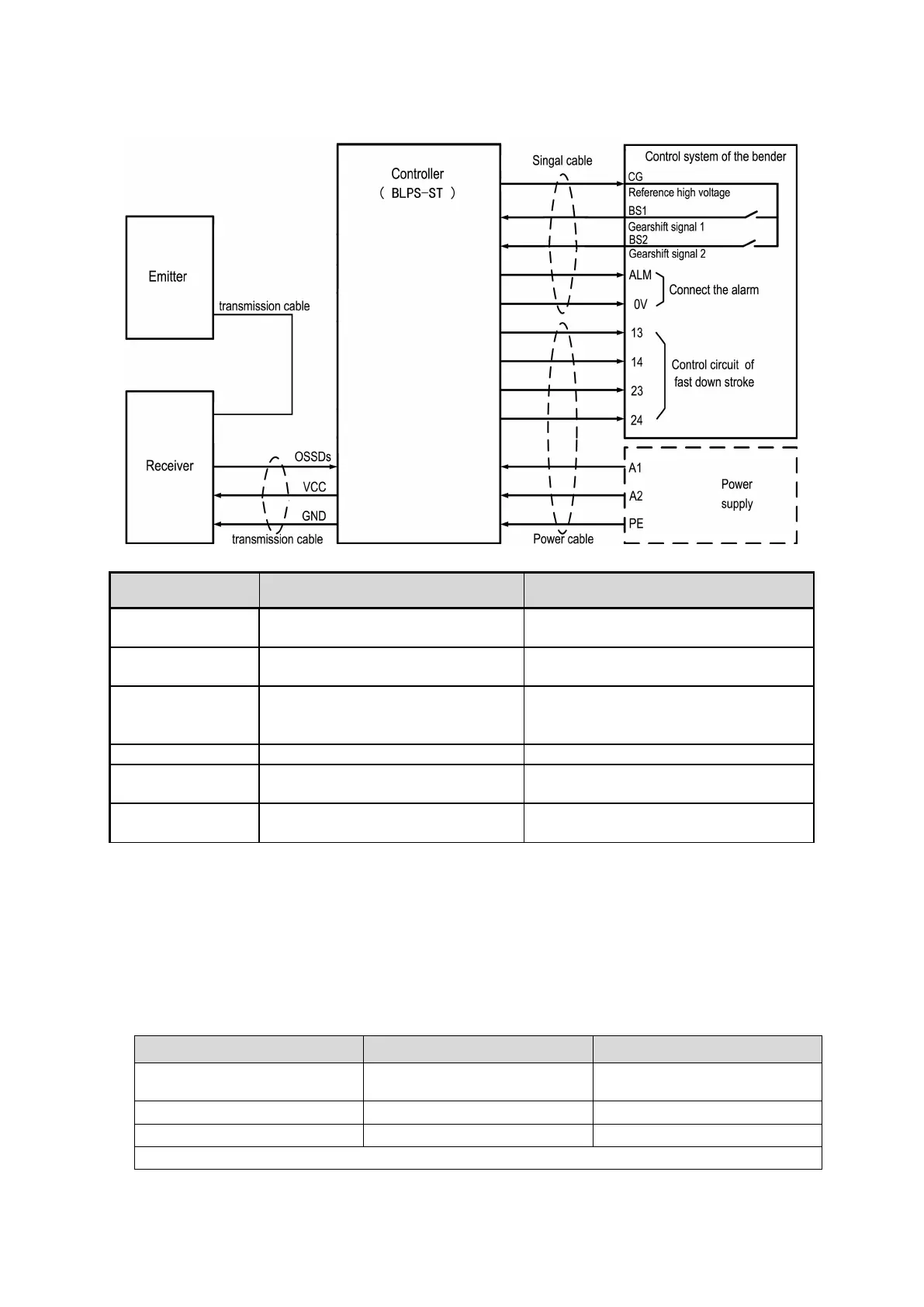
ST controller
Fig.2.3 Interface circuit of ST
Connect to the right power supply
according to the rated voltage
Reference high- level signal output of
the controller
Provide high level voltage for external
relay contacts
Gearshift signal of the bender
Connect to the NO contacts of the relay
which controls the slow down stroke of
the bender
Output signal of the sensor
Connect to the controller
OSSD output signal in the form of
relay output signal
Connect to the circuit which controls the
fast down stroke of the bender
Alarm output signal in the form of
PNP
2.2 Function declaration
2.2.1 Self-test function
BLPS performs the self-test when power is turned ON to check for errors.
If an error is found in the self-test, BLPS enters fault state, keeps the OSSDs on OFF-state,
and indicates the error at the same time.
Self-Test detailed description
Types of errors to be detected
Broken or short-circuited of the
cable
Failure of safety output circuit
Note:● possessed;○ not possessed