- 21 -
SP controller
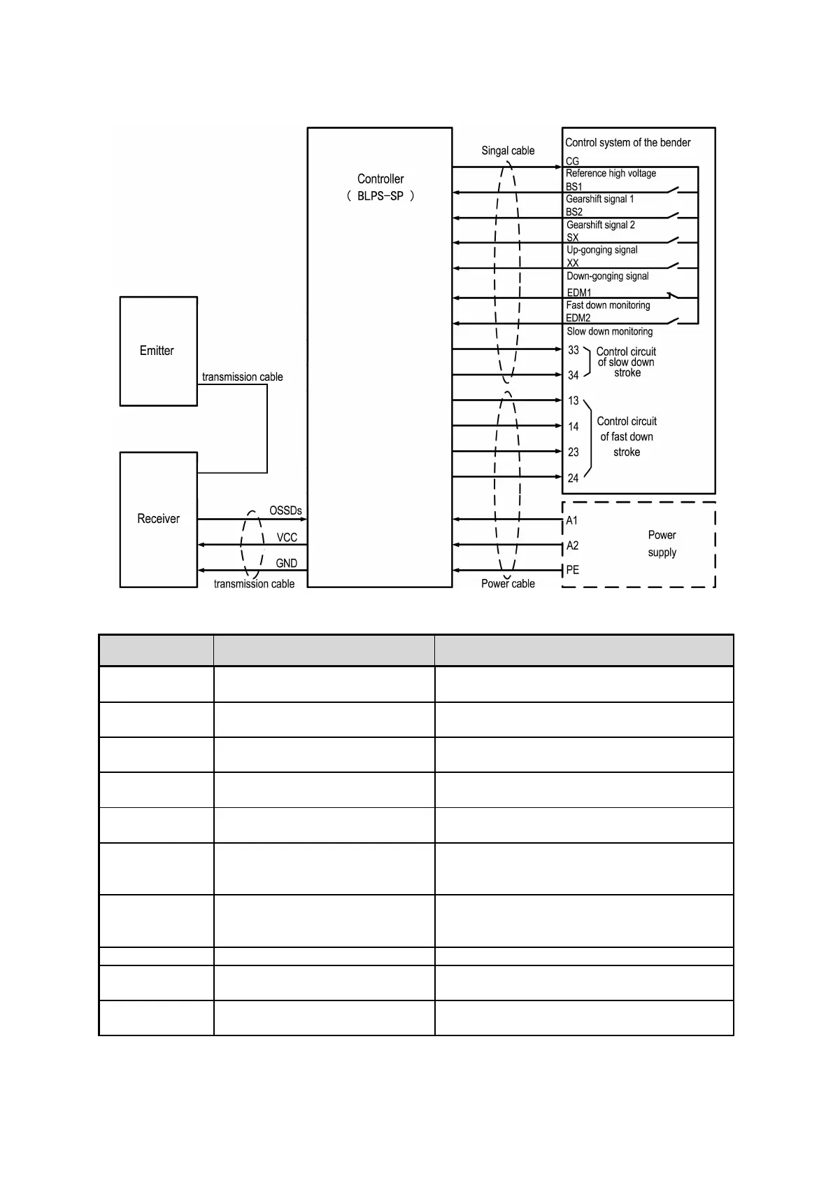
Fig.2.2 Interface circuit of SP
Signal and wiring introduction:
Connect to the right power supply according to
the rated voltage
Reference high- level signal
output of the controller
Provide high level voltage for external relay
contacts
Gearshift signal of the bender
Connect to the NO contacts of the relay which
controls the slow down stroke of the bender
Up running signal of the bender
Connect to the NO contacts of the relay which
controls the up running stroke of the bender
Down running signal of the bender
Connect to the NO contacts of the relay which
controls the down running stroke of the bender
Monitor the state of relay which
controls the fast down stroke of
the bender
Connect to the NO contacts of the relay which
controls the fast down stroke of the bender
Monitor the state of relay which
controls the slow down stroke of
the bender
Connect to the NO contacts of the relay which
controls the slow down stroke of the bender
Output signal of the sensor
Connect to the controller
OSSD output signal in the form of
relay output signal
Connect to the circuit which controls the fast
down stroke of the bender
Output signal in the form of relay
output signal
Connect to the circuit which controls the slow
down stroke of the bender