- 32 -
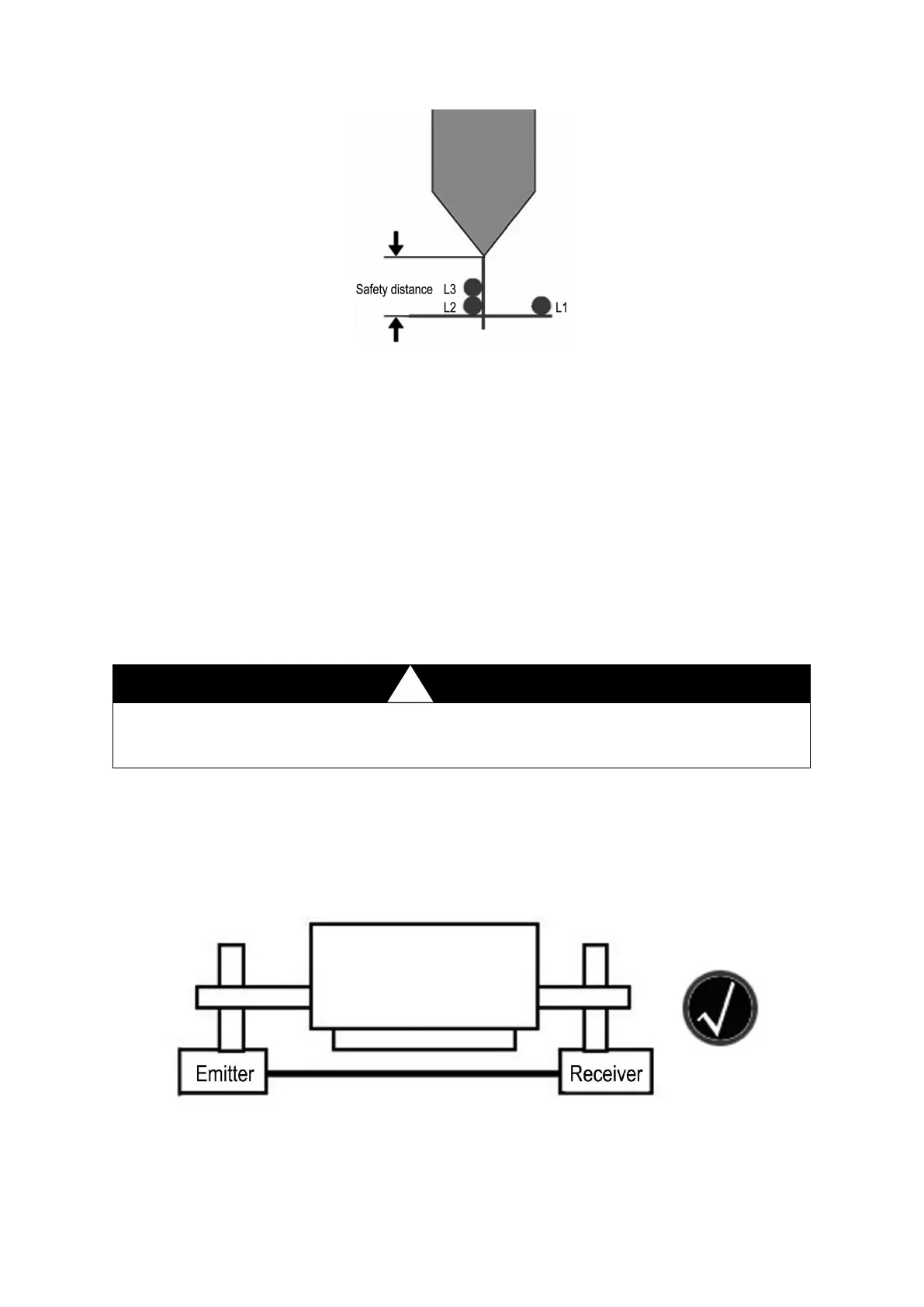
Fig.3.4 Muting point position
S >(t1+t2)×V+5 mm
t1: the response time is less than 8ms
,
when calculating with t1=8ms;
t2: the stopping response time of the bender;
V: the fast downward clamping speed of the bender.
The safety distance S is obtained in the following several ways.
1)Calculated by the formula(S >(t1+t2)×V+5 mm)
2 ) The braking distance measured by the bender grating ruler plus 5mm equals the safe
distance.
3
)
The braking distance measured by the calibrator of BLPS plus 5mm equals the safe
distance(See 3.2.4 chapter).
Note: when the three results are different, choose the maximum value as the safety distance.
The safety distance is one of the necessary conditions to achieve the protection function of
BLPS. Calculation of safety distance must be correct and accurate, it should be ensured
while installing BLPS.
3.2 Installation of sensor
3.2.1 Installation site
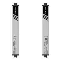
The sensor should is mounted on the both sides of the upper die slider of the bender.
The vertical mounting diagram of the detecting sensor of BLPS.
Right mounting diagram
The emitter and receiver are aligned horizontally, the detecting beam parallels the upper die
tip.