EasyManua.ls Logo

SDKELI BLPS-D3L - User Manual

SDKELI BLPS-D3L
50 pages
Print Icon
To Next Page IconTo Next Page
Loading...
BLPS-D3L Laser Safety Protective Device
Operating manual
May, 2022
Jining Keli Opto-electronic Technology Co., Ltd.

Table of Contents

Questions and Answers

  • T
    tcurryAug 13, 2025
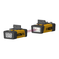
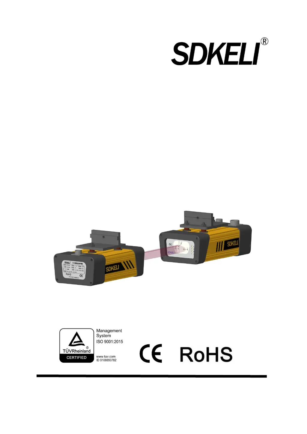
    What to do if SDKELI BLPS-D3L has no red light from the emitter window?
    • R
      russellgregAug 13, 2025
      If the SDKELI Safety Equipment shows no red light from the emitter window, there are several potential causes. It could be due to an emitter fault, in which case you should change the emitter. Alternatively, the receiver might be faulty, requiring you to change the receiver. Finally, the line between the emitter and the receiver could be faulty, so you should perform maintenance on the circuit.
  • A
    Alan WilkersonAug 16, 2025
    What to do if SDKELI Safety Equipment has a dirty clear surface?
    • A
      Amber ThomasAug 17, 2025
      If you notice a dirty clear surface on your SDKELI Safety Equipment, wipe the launch with a clean, soft cotton yarn on the light hole surface of the receiver.
  • H
    Holly CarrAug 21, 2025
    How to fix SDKELI Safety Equipment with light beam L1 not good for light?
    • C
      Craig PerryAug 21, 2025
      If the light beam L1 on your SDKELI Safety Equipment is not optimal, try to refocus it.
  • P
    Philip GallegosAug 25, 2025
    How to fix SDKELI BLPS-D3L Safety Equipment with light beam L2 not good for light?
    • J
      Jason LongAug 25, 2025
      If the light beam L2 on your SDKELI Safety Equipment is not optimal, try to refocus it.
  • C
    Cynthia LittleAug 28, 2025
    How to fix SDKELI Safety Equipment with light beam L3 not good for light?
    • O
      ogoodwinAug 28, 2025
      If the light beam L3 on your SDKELI Safety Equipment is not optimal, try to refocus it.
  • B
    Beth PetersSep 1, 2025
    What to do if SDKELI BLPS-D3L Safety Equipment has OSSD short circuit?
    • K
      kellycookSep 1, 2025
      If your SDKELI Safety Equipment experiences an OSSD short circuit, check the wiring circuit.
  • C
    Chelsea DanielsSep 4, 2025
    What to do if SDKELI Safety Equipment has a receiver fault?
    • J
      Jennifer BrownSep 5, 2025
      If your SDKELI Safety Equipment has a receiver fault, change the receiver.
  • E
    Erik WatersSep 8, 2025
    How to troubleshoot SDKELI Safety Equipment without power source?
    • C
      Crystal MelendezSep 8, 2025
      If your SDKELI Safety Equipment is without a power source, check the power source and wiring circuits.

Summary

Legislation and Standards

User Instructions

Limitations of Liability

Details warranty period, disclaims implied warranties, and limits KELI's responsibility for damages.

Performance

Provides performance data as a guide for user suitability, not a warranty.

Change in Specifications

Informs about potential changes in product specifications and advises contacting the company for details.

Errors and Omissions

States that the manual is as accurate as possible but may contain errors or omissions.

Copyright and Copy Permission

Outlines copyright protection and rules for document reproduction and use.

Precautions on Safety

Precautions for Safe Use

General Precautions

Highlights safety alert symbols (WARNING, CAUTION) and their importance for hazard prevention.

Product Description

Applications

Describes the requirements BLPS objects must meet and environments where it should not be used.

System Components

Lists the main components of the BLPS: detection sensor, controller, and cables.

Sensor Used Alone

Explains that the sensor can be used separately with CNC benders and PLCs.

Specification

System Specification

Provides system-level specifications including installation, power, output, and detection range.

Emitter; Receiver Specification

Details specifications for the emitter and receiver components of the BLPS.

Controller Specification

Outlines the specifications for the different controller types (SR, SP, ST).

Cable Specification

Power&Signal Cable Specification

Details the pinout, length, and type for power and signal cables.

Receiver-Controller Transmission Cable Specification

Specifies the transmission cable connecting the receiver to the controller.

Emitter-Receiver Transmission Cable Specification

Specifies the transmission cable connecting the emitter to the receiver.

Sensor

Appearance

Illustrates the physical appearance and labeling of the BLPS sensor.

Dimensions

Presents the physical dimensions of the BLPS sensor unit.

Controller

Appearance

Illustrates the physical appearance and indicators of the SR/SP controller.

Dimensions

Presents the physical dimensions of the SR/SP and ST controller units.

Cables

Power Cable

Describes the 7-core power cable, its connectors, and core functions.

Signal Cable

Describes the 9-core signal cable for SR/SP and 7-core for ST controllers.

Transmission Cable

Details the transmission cables, including single-end and double-end types.

Mounting Brackets

Technical Parameters

Sensor Technical Parameters

Details the technical specifications specific to the BLPS sensor.

Security Category

Specifies the safety type and executive standards the BLPS complies with.

Optical Characteristics

Lists optical properties such as light source, detecting range, and aperture angle.

Environmental Characteristics

Electrical Characteristics

SR;SP Controller Technical Parameters

ST Controller Technical Parameters

Function Introduction

Input;Output Interface Circuit

Describes the electrical interface circuits for the sensor and controllers.

Interface Circuit of Sensor

Illustrates the input/output interface circuit diagram for the BLPS sensor.

Interface Circuit of Controller

Illustrates the interface circuit diagrams for SR, SP, and ST controllers.

SR Controller

Details the signal and wiring interface circuit for the SR controller.

SP Controller

Details the signal and wiring interface circuit for the SP controller.

ST Controller

Details the signal and wiring interface circuit for the ST controller.

Function Declaration

Self-Test Function

Describes the self-test procedure performed by the BLPS upon power-on.

Monitoring Function

Explains the monitoring capabilities for sensor states and controller relays.

Safety Output

Details the OSSD outputs from the sensor and controller safety relay outputs.

Operating Mode

Sensor Used Alone

Describes the operating mode when the sensor is used independently.

Sensor and SR Controller Used Together

Details operating modes (normal, folding box, muting) with SR controller.

Sensor and SP Controller Used Together

Details operating modes (normal, folding box, muting) with SP controller.

Sensor and ST Controller Used Together

Explains the process conversion timing and modes for ST controller.

Installation and Wiring

Installation Suggestion

Offers general suggestions and considerations for BLPS installation.

Interference Prevention Measures

Discusses measures to prevent reflective surface and external light interference.

Muting Point Setting

Explains how to set the muting point to avoid misidentification of workpieces.

Safety Distance

Defines and explains the calculation of the necessary safety distance for BLPS.

Installation of Sensor

Installation Site

Specifies the recommended installation location for the sensor on the bender.

Mounting Brackets

Illustrates the mounting brackets and their adjustment structures.

Installation Steps

Details the step-by-step procedure for mounting the sensor.

Light Debugging

Explains the process of aligning the sensor beam for optimal detection.

Installation of Controller

Installation of SR;SP Controller

Details the mounting procedure for the SR/SP controller.

Installation of ST Controller

Details the mounting procedure for the ST controller.

Installation of Optional Accessories

Wiring

Wiring Considerations

Outlines important considerations and precautions for BLPS wiring.

Power Supply

Specifies requirements for the power supply to ensure safe and normal operation.

Wiring Procedures

Details the step-by-step procedures for wiring the BLPS components.

Wiring Diagram of Sensor

Presents the wiring diagram for connecting the BLPS sensor.

Wiring Diagram of SR Controller

Presents the wiring diagram for connecting the SR controller.

Wiring Diagram of SP Controller

Presents the wiring diagram for connecting the SP controller.

Wiring Diagram of ST Controller

Presents the wiring diagram for connecting the ST controller.

Check and Debugging

Installation Condition Check

Lists checks to perform on the installation environment and setup.

Wiring Check Before Switching on Power Supply

Details checks for wiring correctness before powering up the system.

Operation Check While the Bender is Stopped

Describes operational checks when the bender is not in motion.

Operation Check While the Bender Operates

Describes operational checks when the bender is in motion.

Maintenance

Inspection at Startup and When Changing Operators

Outlines checks to perform during startup and operator changes.

Inspection for the Guarded Machine

Details checks related to the machine's protective functions and status.

Items to Inspect Every 6 Months or When Machine Settings Are Changed

Lists periodic inspection items for system integrity and settings.

Troubleshooting

Fault Analysis

Provides a table for analyzing common phenomena, causes, and solutions for faults.

Braking System Fault of the Bender

Helps diagnose and resolve issues related to the bender's braking system.

SDKELI BLPS-D3L Specifications

General IconGeneral
BrandSDKELI
ModelBLPS-D3L
CategorySafety Equipment
LanguageEnglish

Related product manuals