Sistemi Elettronici
di Apertura Porte e Cancelli
International registered trademark n. 804888
®
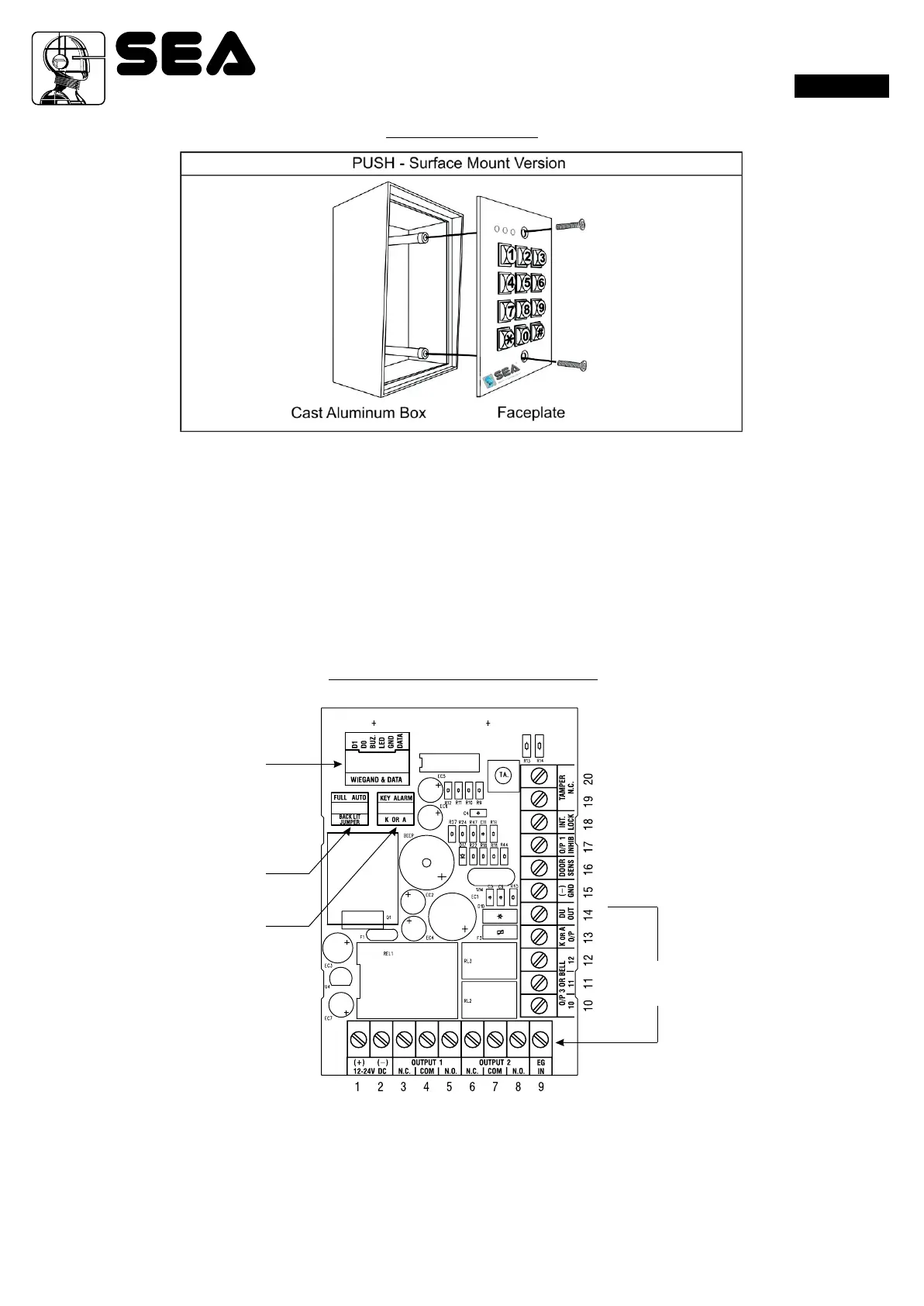
PUSH
English
WIEGAND & DATA
I/O HARNESS
BACK-LIT JUMPER
K OR A JUMPER
CONNECTION
TERMINALS
INSTALLATION
PRECAUTIONS
Please be patient to study the manual to become familiar with the specications of the system before starting the installations.
1) Do not apply power to the system while it is in installation.
2) Check carefully all the wirings are correct before applying power to the system for testing.
PACKAGE CONTENTS
• One unit Keypad
• One pack of Mounting Screws
• One Centre Pin Torx Screw Wrench
• One Wire Harness ( Six wires)
• One Programming & Installation Manual
CONNECTION TERMINALS
• 1 - 2 : 12-24V DC (Power Input Terminal)
Connect to 12-24V DC power supply. The (-) supply and the (-) GND are the common grounding points of the system.
The system accepts full input voltage range with no jumper selection.
• 3 - 4 - 5 : OUTPUT 1 (Output Relay 1)
5 Amp relay dry contact controlled by the Group 1 User PINs for Output 1, recommended for door strike. Terminal 3 is Normally
Closed (N.C.), terminal 5 is Normally Open (N.O.) and terminal 4 is the common point of the two contacts.
Use N.C. output for “Fail-safe” locking device; and N.O. output for “Fail-secure” locking device. The relay is programmable for
Start/Stop (toggle) mode or Momentary timing mode. See programming Location 51 for the details.
31Rev. 01 - 05/201167411245