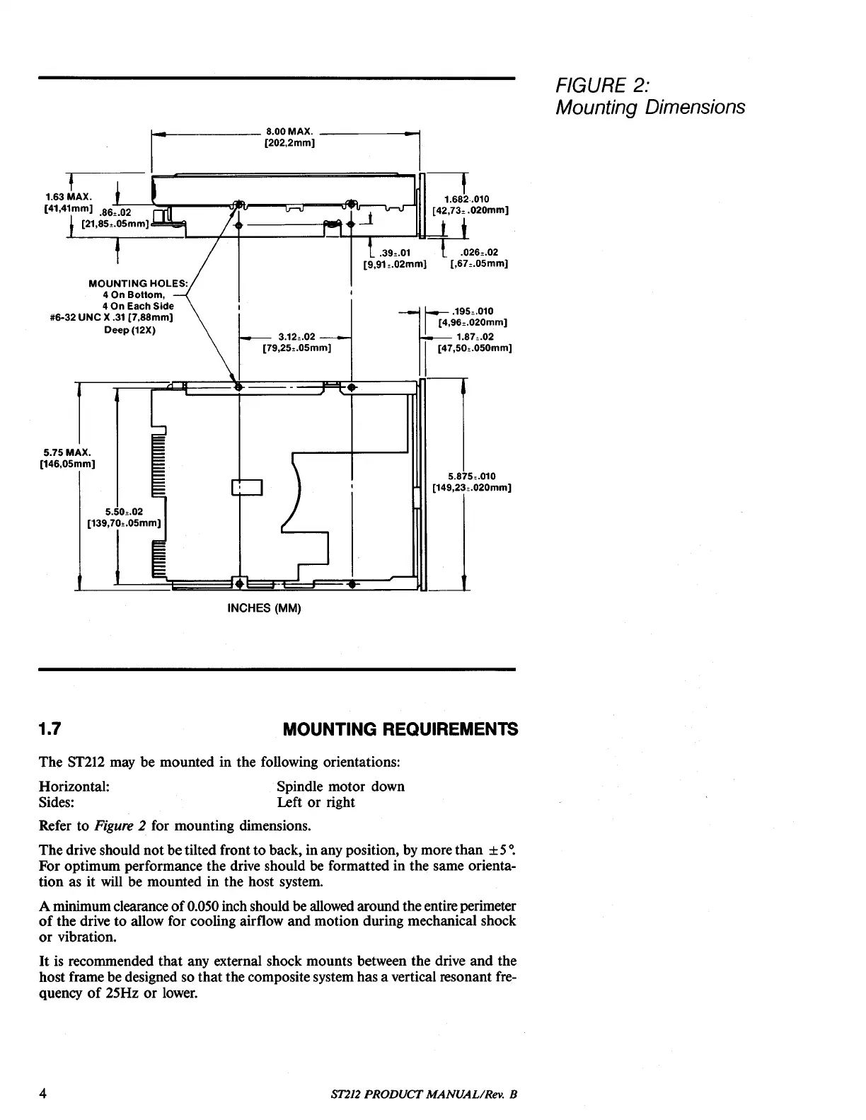
FIGURE 2:
Mounting Dimensions
r
'
195
"010
1
[4,96,.020mm)
1.87,.02
1
[47,50,.050mm)
---,
1.682
..
010
[42,73,
.020mm)
.39,.01
~26"02
[9,91,.02mm)
[,67,.05mm)
..
1
k 3.12,.02
1
[79,25,.05mm)
_------
8.00
MAX.
......
_,
[202,2mm)
MOUNTING
HOLES:
40n
Bottom,
4
On
Each Side
#6-32
UNe
X
.31
[7,88mm)
Deep(12X)
m
5.75
MAX.
[146,05mm)
5.50,.02
[139,70,.05mm)
5.875,.010
[149,23,.020mm)
INCHES (MM)
1.7
MOUNTING REQUIREMENTS
The
ST212
may be mounted in the following orientations:
Horizontal: Spindle motor down
Sides: Left
or
right
Refer to
Figure
2 for mounting dimensions.
The drive should not be
tilted front to back, in any position, by morethan ± 5
o.
For optimum performance the drive should be formatted in the same orienta-
tion as it
will
be mounted in the host system.
A minimumclearance
of
0.050 inch should be allowed around theentire perimeter
of
the drive to allow for cooling airflow and motion during mechanical shock
or
vibration.
It
is recommended that any external shock mounts between the drive and the
host frame be designed so
that
the composite system has a vertical resonant fre-
quency
of
25Hz
or
lower.
4
ST212
PRODUCT MANUAL/Rev. B