4.0
CONTROL
INPUT SIGNALS
The control signaIs are
of
two types: those to be multiplexed in a multiple drive
system and those intended
to
do
the multiplexing.
The signaIs to be multiplexed are WRITE GATE, HEAD SELECT
2°,
HEAD
SELECT 2
1
,
HEAD
SELECT 2
2
,
HEAD
SELECT
23,
DIRECTION IN,
and
STEP. These
Hnes
are terminated with a removable 220/330
{}
resistor pack.
The multiplexing signaIs are DRIVE SELECT l, DRIVE SELECT
2,
DRIVE
SELECT
3,
and
DRIVE SELECT4. These
Hnes
are terminated in a single
flXed
220/330
{}
resistor pack.
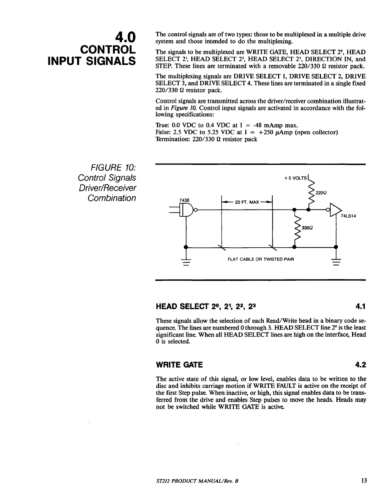
Control signaIs are transmitted across the driver/receiver combination illustrat-
ed
in
Figure
10.
Control input signaIs are activated in accordance with the fol-
lowing specifications:
True: 0.0 VDC to 0.4 VDC
at
1 =
-48
mAmp max.
FaIse: 2.5 VDC
to
5.25 VDC
at
1 = +250
JLAmp
(open collector)
Termination: 220/330
{}
resistor pack
FIGURE
10:
Control Signais
Driver/Receiver
Combination
7438
20
FT.
MAX
FLAT CABLE
OR
TWISTED PAIR
HEAD SELECT
20,
2
1
,
2
2
,
2
3
4.1
These signaIs aIlow the selection
of
each Read/Write head
in
a binary code se-
quence. The
Hnes
are numbered 0 through
3.
HEAD SELECT
Hne
2°
is the least
significant
Hne.
When aIl
HEAD
SELECT
Hnes
are high
on
the interface,
Head
o
is
selected.
WRITE GATE
4.2
The active state
of
this signal,
or
low level, enables data
to
be written
to
the
disc and inhibits carriage motion
if
WRlTE
FAULT
is active
on
the receipt
of
the first Step pulse. When inactive,
or
high, this signaI enables
data
to be trans-
ferred from the drive
and
enables Step pulses
to
move the heads. Heads may
not
be switched while
WRlTE
GATE is active.
8T212 PRODUCT MANUAL/Rev. B
13