9.1.1
DIFFERENTIAL READ FILTER: TEST POINTS 1 AND 2
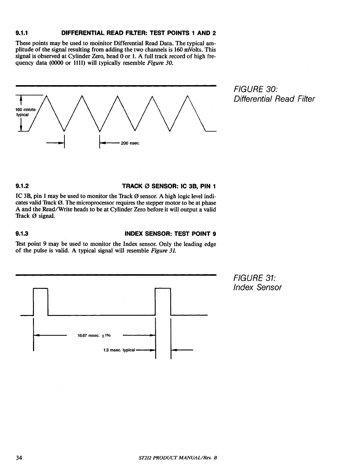
These points may be used to moinitor Differential Read Data. The typical am-
plitude
of
the signal resulting from adding the two channels
is
160
mVolts. This
signal is observedat Cylinder Zero, head 0
or
1.
A full track record
of
high fre-
quency
data
(0000
or
1111)
will typically resemble Figure 30.
FIGURE 30:
DifferentiaI Read Filter
9.1.2
TRACK
0 SENSOR: IC
38,
PIN 1
IC
3B,
pin 1may be used to monitor the Track 0 sensor. A high logic
level
indi-
cates valid Track
0.
Themicroprocessor requires the stepper motor to he at phase
A
and
the Read/Write heads to be
at
Cylinder Zero before it will output a valid
Thlck 0 signal.
9.1.3
INDEX SENSOR: TEST POINT 9
lest
point 9 may be used to monitor the Index sensor. Only the leading edge
of
the pulse
is
valid. A typical signal will resemble Figure
31.
16.67
msec. ±1%
1.3
msec.
typical-_-I
FIGURE
31:
Index Sensor
34
ST212
PRODUCT
MANUALIRev. B