Sl'sec max.
l
.
.1
(head
sWitc~
READ DATA
+MFM
VALID
4.3
- DRIVE SELECT
I~-----""""f
ft------
- HEAD SELECT
I~-----""""f
ft------
-1
/---25nsec
min.
............
........MfL
--t
~~::Ccell)
~
~~t~r
--"'W~R~IT~E"'!G!""!'A~TE~-"''''''---~I
f
~
L .1'
~
1 L 50nsec min.
400nsec
max.
TI
-,
r150nsec
max.
_+_M_F_M_W_R_'T_E~D~A~TA
__
~
I1JUlI.
_
(precompensated
12nsec)
1 1
(;~~i)I
r
STEP
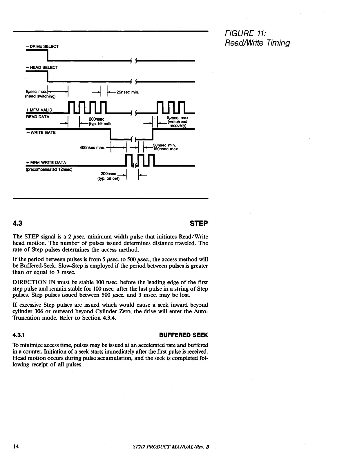
FIGURE
11:
ReadlWrite Timing
The
STEP
signal is a 2 p,sec.
minimum
width
pulse
that
initiates
Read/Write
head
motion.
The
number
of
pulses issued determines distance traveled.
The
rate
of
Step pulses determines
the
access
method.
If
the
period
between pulses is
from
5 p,sec.
to
500 p,sec.,
the
access
method
will
be
Buffered-Seek. Slow-Step is employed
if
the
period
between pulses is greater
than
or
equal
to
3 msec.
DIRECTION
IN
must
be
stable 100 nsec. before
the
leading edge
of
the
first
step
pulse
and
remain
stable
for
100 nsec.
after
the
last pulse
in
a string
of
Step
p.ulses.
Step
pulses issued between 500 p,sec.
and
3 msec.
may
be
lost.
If
excessive Step pulses
are
issued which would
cause
a seek inward beyond
cylinder 306
or
outward
beyond
Cylinder
Zero,
the
drive will
enter
the
Auto-
'll:uncation mode. Refer
to
Section 4.3.4.
4.3.1
BUFFERED SEEK
Th minimize access time, pulses may
be
issued at
an
accelerated
rate
and
buffered
ina counter. Initiation
of
a seek starts immediately after
the
frrst pulse is received.
Head
motion
occurs
during
pulse
accumulation,
and
the
seek is
completed
fol-
lowing receipt
of
all pulses.
14
ST212
PRODUCT
MANUALIRev. B