The
ST212
may be configured for specific system requirements. These options
are detailed in
Sections 3.1 through 3.5.
3.0
DRIVE
CONFIGURATION
DRIVE CONFIGURATION: SHUNT J9 (MLC-01) 3.1
J9 is a 16-pin right-angle shunt located midway between
JI
and J2. Use the
provided shorting blocks to enable the DRIVE SELECT
Hnes
and any required
option.
Figure
7 illustrates J9 and indicates pin
1.
EarHer drives employed a shunt which required cutting the jumpers
to
enable
DRIVE SELECT.
To
enable
DS1,
for example, cut DS2,
DS3
and DS4. Refer
to
Figure
7.
DRIVE SELECT
3.2
The DRIVE SELECT
Hne
enables the controller to select and address the drive.
Pins
1-2
shorted enable ï>RIVE SELECT 1
Pins 3-4 shorted enable DRIVE SELECT 2
Pins
5-6
shorted enable DRIVE SELECT 3
Pins
7-8
shorted enable DRIVE SELECT 4
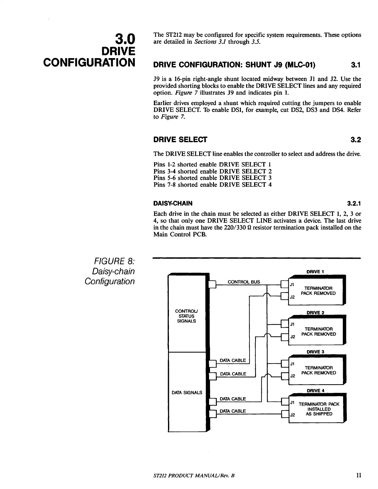
DAISY-CHAIN 3.2.1
Each drive in the chain must be selected
as
either DRIVE SELECT
1,
2,
3
or
4,
so that only one DRIVE SELECT
UNE
activates a device. The last drive
in the chain must have the 220/330
{}
resistor termination pack installed
on
the
Main Control PCB.
FIGURE
8:
Daisy-chain
DRIVE 1
Configuration
CONTROL BUS
J1
TERMINAlOR
PACK REMOVED
J2
CONTROU
DRIVE 2
STATUS
SIGNALS
J1
TERMINAlOR
J2
PACK REMOVED
DRIVE 3
DATA
CABLE
J1
TERMINAlOR
DATA
CABLE
J2
PACK REMOVED
DATA
SIGNALS
DRIVE 4
DATA
CABLE
J1
TERMINAlOR
PACK
DATA
CABLE
INSTALLED
J2
AS SHIPPED
ST212 PRODUCT MANUAL/Rev. B
11