7.2
CONTROLLER
STEP
DIRECTION
HEAD SELECT
0,1,2
MPU:
PC
BOARD 20243-XXX
CONTROLLER
SEEK·
COMPLETE
READY
TRACK
0
STEPPER
CIRCUIT
FIGURE
26:
MPU: PC Board
20243-XXX
INDEX
CIRCUIT
TRACK
0
CIRCUIT
MPU
IWR
MOTOR
ON
STEPPER
MOTOR
WRITE
CIRCUIT
MOTOR
PCB
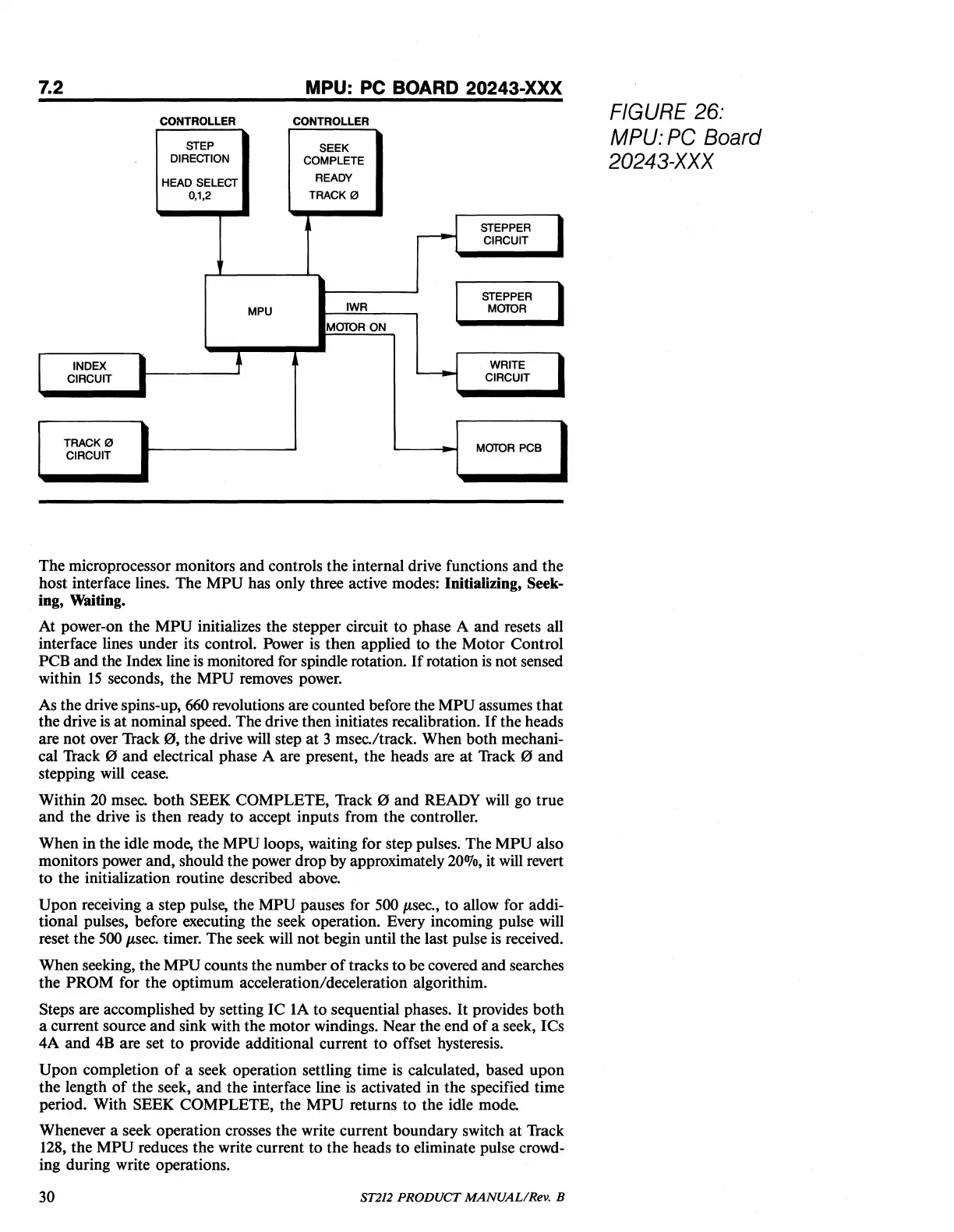
The
microprocessor monitors
and
controls
the
internaI drive functions
and
the
host
interface lines.
The
MPU
has only three active modes: Initializing, Seek-
ing, Waiting.
At
power-on
the
MPU
initializes the stepper circuit
to
phase A
and
resets aIl
interface lines
under
its control. Power is
then
applied
to
the
Motor
Control
PCB
and
the Index line is monitored for spindle rotation.
If
rotation
is
not
sensed
within
15
seconds,
the
MPU
removes power.
As the drive spins-up, 660 revolutions are counted before the
MPU
assumes
that
the
drive is
at
nominal speed. The drive
then
initiates recalibration.
If
the
heads
are
not
over Track
0,
the
drive will step
at
3 msec./track.
When
both
mechani-
cal Track
0
and
electrical phase A are present,
the
heads are
at
Track 0
and
stepping will cease.
Within
20 msec.
both
SEEK
COMPLETE,
Track 0
and
READY will go
true
and
the
drive is
then
ready
to
accept
inputs
from
the
controller.
When
in
the idle mode,
the
MPU
loops, waiting for step pulses.
The
MPU
also
monitors power and, should the power
drop
by
approximately
20070,
it will revert
to
the
initialization routine described
ab
ove.
Upon
receiving a step pulse,
the
MPU
pauses for 500 p,sec.,
to
allow for addi-
tional pulses, before executing the seek operation. Every incoming pulse will
reset
the
500
p,sec.
timer.
The
seek will
not
beginuntil
the last pulse is received.
Wh
en seeking,
the
MPU
counts the number
of
tracks
to
be covered
and
searches
the
PROM
for
the
optimum
acceleration/deceleration algorithim.
Steps are accomplished by setting
IC
lA
to
sequential phases.
It
provides
bath
a current source
and
sink with
the
motor
windings.
Near
the
end
of
a seek, ICs
4A
and
4B are set
to
provide additional current
to
offset hysteresis.
Upon
completion
of
a seek operation settling time is calculated, based
upon
the
length
of
the
seek,
and
the
interface line
is
activated
in
the
specified time
periode
With
SEEK
COMPLETE,
the
MPU
returns
to
the
idle mode.
Whenever a seek operation crosses
the
write current
boundary
switch
at
Track
128,
the
MPU
reduces
the
write current
to
the
heads
to
eliminate pulse crowd-
ing
duringwrite
operations.
30
ST212
PRODUCT
MANUAL/Rev.
B