1\\'0 pairs
of
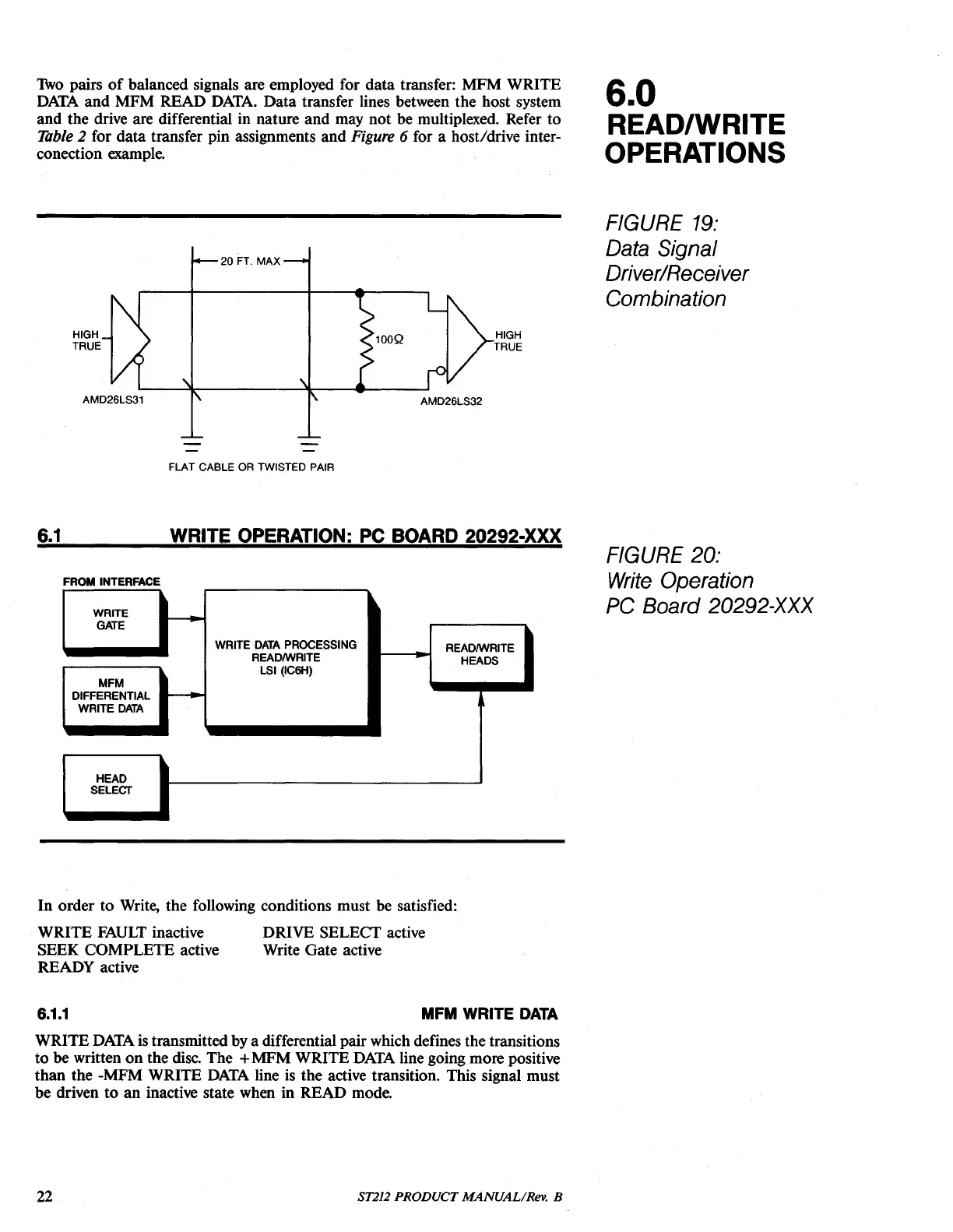
balanced signaIs are employed for data transfer: MFM WRITE
DATA
and
MFM READ
DATA.
Data transfer
Hnes
between the host system
and the drive are differential in nature and may not be multiplexed. Refer to
1àble 2 for data transfer pin assignments and Figure 6 for a host/drive inter-
conection example.
6.0
READ/WRITE
OPERATIONS
20 FT.
MAX
HIGH
TRUE
FIGURE
19:
Data
Signal
Driver/Receiver
Combination
FLAT CABLE
OR
TWISTED PAIR
6.1
WRITE
OPERATION:
PC
BOARD
20292-XXX
WRITE
GATE
WRITE
DATA
PROCESSING
READIWRITE
READIWRITE
HEADS
LSI (IC6H)
MFM
DIFFERENTIAL
WRITE
DATA
HEAD
SELECT
FIGURE
20:
FROM
INTERFACE
Write
Operation
PC
Board 20292-XXX
In
order to Write, the following conditions must be satisfied:
WRITE
FAULT
inactive
SEEK COMPLETE active
READY active
DRIVE SELECT active
Write Gate active
6.1.1
MFM
WRITE
DATA
WRITE
DATA
is
transmitted by a differentiai pair which defines the transitions
to
be written
on
the
disco
The +MFM WRlTE
DATA
Hne
going more positive
than
the -MFM WRITE
DATA
Hne
is
the active transition. This signal must
be driven
to
an
inactive state when in READ mode.
22
ST212 PRODUCT MANUALIRev. B