9.3.3
INDEX SENSOR REMOVAL
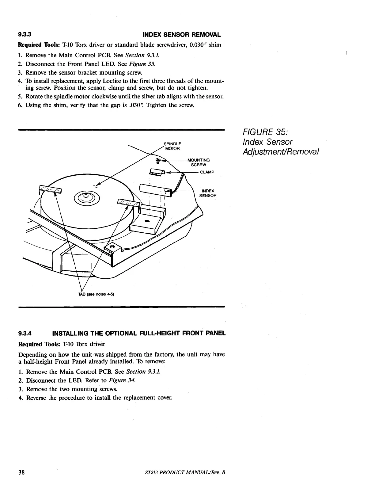
Required Tools: T-lOTorx driver or standard blade screwdriver, 0.030" shim
1.
Remove the Main Control PCB. See Section
9.3.1.
2.
Disconnect the Front Panel LED. See Figure 35.
3.
Remove the sensor bracket mounting
screw.
4.
To
install replacement, apply Loctite to the first three threads
of
the mount-
ing
screw.
Position the sensor, clamp and
screw,
but do not tighten.
5.
Rotate the spindle motor clockwise until the silver tab aligns with the sensor.
6.
Using the shim, verify that the gap
is
.030'~
Tighten the
screw.
'l!!"-
......
--,MOUNTING
SCREW
i::z:::,...J.J--=~--
CLAMP
!.-Q'#---\--INDEX
SENSOR
TAB
(see notes
4-5)
9.3.4 INSTALLING THE OPTIONAL FULL-HEIGHT FRONT PANEL
Required Tools:
T-IO
Torx driver
Depending on how the unit
was
shipped from the factory, the unit may have
a half-height Front Panel already installed.
To
remove:
1.
Remove the Main Control PCB. See Section
9.3.1.
2.
Disconnect the LED. Refer to Figure 34.
3.
Remove the two mounting
screws.
4.
Reverse the procedure to install the replacement
coyer.
FIGURE 35:
Index Sensor
AdjustmentiRemoval
38
ST212 PRODUCT MANUAL/Rev. B