9.2.2
READ
DATA:
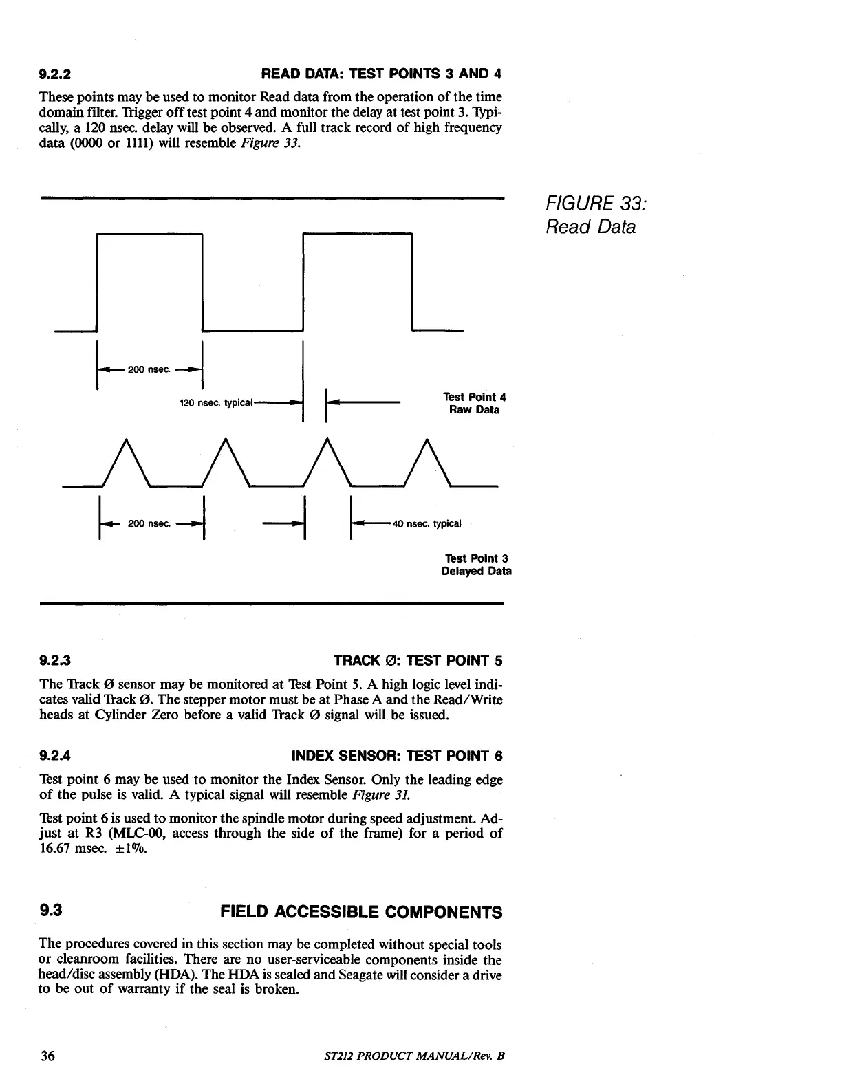
TEST POINTS 3 AND 4
These points may be used
to
monitor Read
data
from the operation
of
the time
domain filter.
liigger
off
test point 4 and monitor the delay at test point 3. Typi-
cally, a 120 nsee. delay will be observed. A full track record
of
high frequency
data
(0000
or
1111)
will resemble Figure 33.
FIGURE
33:
Read Data
Test Point 4
Raw Data
Test Point 3
Delayed Data
9.2.3
TRACK
0:
TEST POINT 5
The
lfack
0 sensor may be monitored
at
lèst
Point
5.
A high logic level indi-
cates valid Track
0.
The stepper motor must be
at
Phase A
and
the Read/Write
heads
at
Cylinder Zero before a valid
lfack
0 signal will
be
issued.
9.2.4
INDEX SENSOR: TEST POINT 6
Test point 6 may be used to monitor the Index Sensor. Only the leading edge
of
the pulse
is
valid. A typical signal will resemble Figure 3J.
Test point 6 is used to monitor the spindle motor during speed adjustment. Ad-
just
at
R3
(MLC-OO,
access through the side
of
the frame) for a period
of
16.67 msec.
±IOJo.
9.3
FIELD ACCESSIBLE COMPONENTS
The procedures covered in this section may be completed without special tools
or
cleanroom facilities. There are
no
user-serviceable components inside the
head/disc assembly (RDA). The
RDA
is
sealed and Seagate will consider a drive
to
be
out
of
warranty
if
the seal
is
broken.
36
ST212 PRODUCT MANUAL/Rev. B