Site Survey
FlexZone Product Guide Page 13
Site Survey
Conduct a site survey to ensure that site conditions are suitable for a FlexZone sensor system.
The primary concern is the condition of the fences and gates. Use the results of the site survey to
create a site plan.
Indicate the following on the site plan:
• The locations of existing structures (include fences, gates, buildings, roads, etc.). Verify that
mounting surfaces comply with established standards for installation and stability.
• The locations of obstacles including vegetation and trees.
• The locations for the FlexZone components:
• Sensor cable - indicate the cable layout and zone boundaries for each sensor cable.
• Non-detecting cable - indicate the layout if non-detecting cable is required (at the
processor, or for a bypass).
• Cable connectors - indicate the type of connection (splice, termination).
• FlexZone processors - note the addresses for network based processors.
Note Sites that include a fence line that abuts the primary perimeter
fence can be vulnerable to climb over intrusions where the two
fences meet. To increase security in this situation, extend the
FlexZone cable for at least 2 m onto the abutting fence.
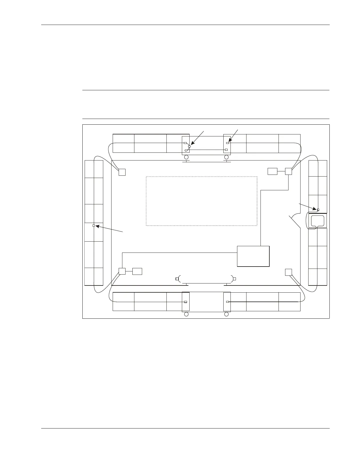
Figure 5: Sample site plan
gate disconnect
terminator (typical)
sally port gate
proc #2
swinging gate
proc #1
proc #4
proc #3
power and data over
sensor cable connection
- app. max. fence length per cable 270 m (886 ft.)
microwave sensor
main
building
- drip loops at each splice/termination
- service loop every 50 m
- sensitivity loops at corner posts
sally port
gate
Z15Z12
Z10
48 VDC
48 VDC
Z1
Z2
Z3
Z4
Z5
Z6
Z7
Z8
Z9
Z11
Z13
Z14
Z16
Z17
Z18
Z19
Z20
data cable
data cable
- 19 FlexZone sensor zones (software defined)
- 1 UltraWave microwave zone (Z3)
power and data
over sensor cable
connection